Thursday, April 27, 2017

Implementing Passive CWDM to Upgrade Access PONs

Coarse Wavelength Division Multiplexing (CWDM) has proven itself to be a preferred approach to elevate the bandwidth of optical access networks, offering quicker and simpler installation and lower overall cost. Passive CWDM, which requires no electrical power at all, is considered reliable and robust to deploy in the most demanding environment. It generally offers lower cost and more flexible installation and network expansion. This article demonstrates how to use passive CWDM technology to upgrade access PONs.
Why Passive CWDM for Access PONs?
Passive CWDM is an implementation of CWDM that uses no electrical power. It separates the wavelengths using passive optical components. CWDM multiplexing components are compact enough to easily retrofit into existing fiber splice cassettes for installation into street cabinets or other forms of outside enclosure. Besides, it also processes the following merits:
  • Predictably low equipment and operating cost
  • Quick and efficient network upgrade
  • Simplicity of specification and simplicity of deployment
  • Sufficiently flexible solutions that facilitate expansion
  • Open standards, nothing proprietary
CWDM and Add/Drop With Access PONs
For PON networks, be it in the ring or point-to-point structures, not all capacity is needed at a single optical node. Therefore, data transported over certain channels may be added/dropped from the fiber as required. And it may be implemented at any CWDM node at any location in the field. The picture below illustrates how to achieve this. This is generally cost effective and simple to perform. A passive CWDM upgrade simply eliminates the need for deployment of additional network equipment.
cwdm add drop with access pons
The advantages of the PON architecture above lies in the low CAPEX, low OPEX and no electrical power required. And that it can be quickly and inexpensively upgraded when additional bandwidth demands arise.
How to Upgrade Access PONs With Passive CWDM?
With the prevalence of FTTH networks, access networks between the central office (CO) and the subscribes must be upgraded to keep pace with the hunger bandwidth. The figure below shows a typical PON architecture, with an optical line terminal (OLT) located in the CO to transmit traffic to approximately 16 to 32 residential drop points, and PON splitters located at fiber distribution hubs between the OLTs and subscribers’ optical network terminals (ONTs), enabling one OLT port and laser transceiver to be shared across many drop points.
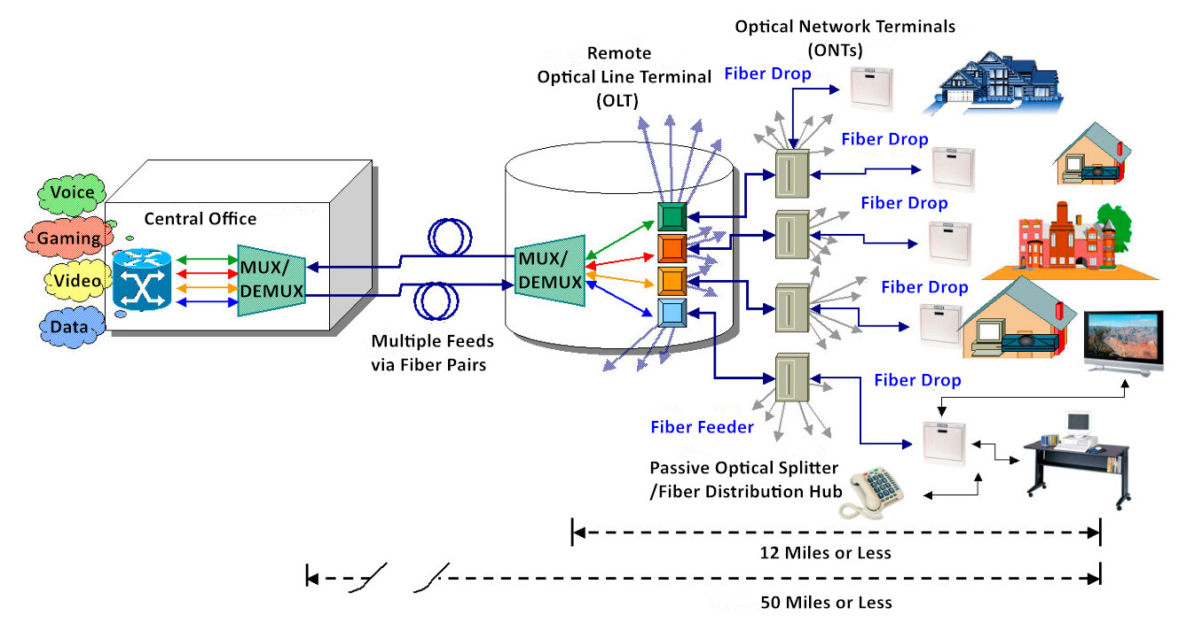
generic pon network using remote olts
Passive CWDM enables better fiber capacity utilization and supports far greater data traffic as the bandwidth demands from the ONTs increase. It permits network operators to implement many more optical nodes over multiple locations with minimal capital investment and virtually no additional operating cost. The following case presents how to use passive CWDM for access PONs upgrade.
Case: In this case, existing subscribers intend to upgrade to higher value-added bandwidth services. The 622 Mb/s downstream capacity between the CO and the OLT, appropriately 20 Mb/s to each subscriber is proven insufficient, which must to increase.
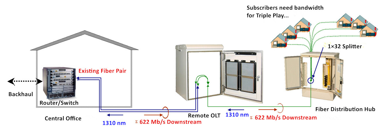
limited fiber capacity in pon
Solution: The adequate bandwidth requires a downstream CO/OLT link bandwidth of 2.5 Gb/s. Multiplying the number of bidirectional channels traveling between the CO and OLT by four demands four CWDM wavelengths. The upgraded passive CWDM based network (shown below) relives the fiber exhaust and boosts the bandwidth of the CO/OLT link. This installation requires four channel-specific (color coded) transceivers plugging into the router/switch, the associated patch cables, the rack-mounted CWDM module and the snap in passive CWDM cassette located in the OLT.
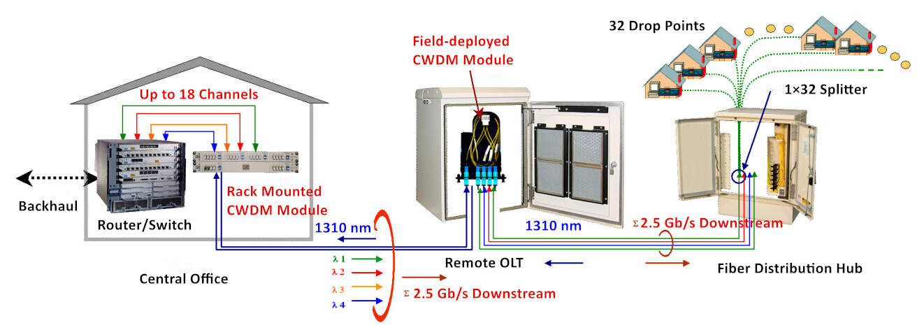
passive cwdm adds capacity in pon
Benefits: The passive CWDM upgrade can be accomplished within hours, while the cost concerning material, labor, equipment and training is far less than that of laying a new fiber cable. Which is both energy-saving and cost-efficient.
Using CWDM to Expand EPON Bandwidth
Passive CWDM is also beneficial to Ethernet PON (EPON). Let’s see how it works in EPON through the case below.
Case: The figure below shows a common EPON architecture, which serves up to 64 subscribers, all sharing a single 1.25Gbps bidirectional optical Ethernet feed line. The theoretical maximum sustainable data-rate for each is roughly 16 Mb/s. The 16Mb/S downstream capacity should be increased since higher bandwidth services become available.
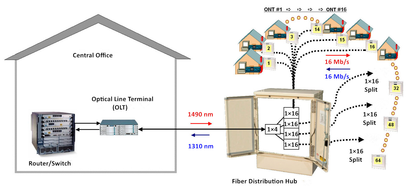
epon deployment
Solution: A four channel passive CWDM extension effectively multiplies the downstream capacity without affecting the upstream traffic. A rack-mounted CWDM unit in the CO and a miniature hardened CWDM module deployed in the fiber distribution hub increases the revenue earning potential while minimizes OPEX and CAPEX.
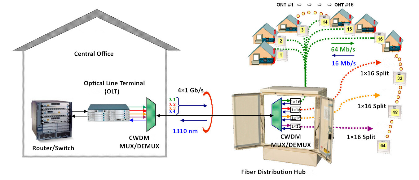
passive cwdm in epon
Benefits: In this case, the four channel CWDM upgrade promotes the throughput of the downlink by a factor of four while demanding minimal modification of the existing infrastructure.
Conclusion
A passive CWDM method provides the unique advantages of low CAPEX, minimal OPEX and rather simple yet reliable upgrade planning and implementation. More importantly, passive CWDM also preserves scalability and network flexibility for future network expansion and bandwidth demand changes. Hope this article is informative enough for getting a better understanding towards passive CWDM.
Wednesday, April 19, 2017

Hybrid CWDM-DWDM System Boosts Your Network Capacity

Should I choose a medium capacity but more cost-effective CWDM solution, or to adopt the cost-prohibitive DWDM approach with comparably enhanced capacity? This is a problem that consistently faced by WDM technology users. The wrong decision, however, may inevitably lead to bandwidth shortage or even potential bankruptcy derived from unnecessary capacity investment. This article introduces the hybrid CWDM-DWDM solution that combines both CWDM and DWDM technologies within a single system, helping decrease costs and simplify installation while maintain the flexibility to upgrade.
Hybrid CWDM-DWDM System Explanation
Hybrid CWDM-DWDM system utilizes the technology to merge DWDM and CWDM traffic seamlessly at the optical layer. Which allows carriers to add many channels to networks originally designed for the more limited CWDM capacity and reach. In other words, hybrid CWDM-DWDM system is used to empower CWDM system by integrating CWDM and DWDM equipment. Hybrid CWDM-DWDM system deliver true pay-as-you-grow capacity growth and investment protection. It offers a simple, plug-and-play option for creating hybrid system of DWDM channels interleaved with existing CWDM channel plans.
Benefits of Hybrid CWDM-DWDM System
Hybrid CWDM-DWDM system typically provides three benefits for carriers and users:
  • Reduced Cost: CWDM is more cost-effective than DWDM due to the lower cost of lasers and the filters used in CWDM modules. This cost saving becomes quite significant for large deployments.
  • Pay-As-You-Grow: Adding one new channels at a time allows for on-demand service introduction with minimal initial investment—a critical feature in terms of reduced OPEX and CAPEX spending.
  • Investment Protection: Carriers and end-users need always to bear the future growth in mind. With hybrid CWDM-DWDM system, carriers no longer have to choose between CWDM and DWDM—both options can be deployed simultaneously or as part of future growth. This module can be used in either CWDM or DWDM system. Current capital investment can always be used in the upgraded network.
How to Deploy Hybrid CWDM-DWDM System
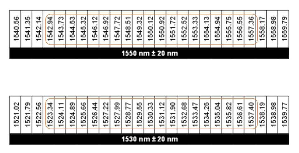
The CWDM wavelength grid typically has 16 channels spacing at 20 nm intervals, with 8 channels (1470 nm-1610 nm) of them are most commonly used. Within the pass band of these channels, it is capable of adding 25 100 GHz spaced DWDM channels under the 1530nm envelope and 25 more under the 1550nm envelope. However, it is not so practical to add 25 DWDM channels in the pass-band of both the 1530nm and 1550nm CWDM channels. DWDM filter technology does allow 38 additional channels to clear the CWDM archway, which is shown as following.
hybrid CWDM-DWDM systems
To add more DWDM channels to the MUX side of the conventional CWDM system, one need to plug in a DWDM MUX with the appropriate channels under the pass band of the existing CWDM filters. The picture below illustrates the configuration of a CWDM system upgraded with 38 additional 100 GHz spaced DWDM channels. This hybrid CWDM-DWDM system consists of 38 DWDM channels and the existing 6 CWDM channels. The equipment required to go from the first architecture to the second are 2 DWDM MUX/DEMUXs, as well as the additional transmitter and receiver pairs. The additional loss incurred by the upgrade is equal to the additional loss of the DWDM elements and the additional connection points.
44-channel-hybrid-CWDM-DWDM-systems
Flexible Hybrid CWDM-DWDM System Solution by FS.COM
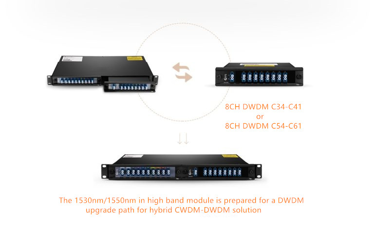
The most vital elements concerning hybrid CWDM-DWDM system are the CWDM MUX/DEMUX and DWDM MUX/DEMUX. FS.COM developed and introduces FMU series products to facilitate installation and operation of WDM MUX/DEMUX. The prominent feature of this series products is that they combine the MUX/DEMUX into half-U plug-in modules, which can be installed in a 1U rack. As for hybrid CWDM-DWDM system, a FMU CWDM MUX/DEMUX and a DWDM half-U plug-in module can be installed together in a FMU 1U rack chassis, facilitating connections of these two modules while allowing for better cable management and network operation in hybrid CWDM-DWDM system.
fmu-dwdm-cwdm-hybrid-solution
Conclusion
Hybrid CWDM-DWDM system generally offers a cost-effective and future-proofing approach for service providers and end-users, by overcoming the obstacles faced by users of WDM technology today, providing a starting platform that scales smoothly and protecting the investment. A user can commence with the more cost-effective CWDM technology and then later add DWDM in the when the capacity is required. FS.COM FMU series WDM solution makes the process even easier and more flexible. For more information, please visit www.fs.com or contact sales@fs.com.

Saturday, April 8, 2017

Extending DWDM Network Reach With Raman Amplifier

Raman amplifier is appearing to be a critical technology which is consistently developed for using in optical communication networks. Typically applied in long-haul networks, Raman amplifier is also expected to extend its reach in dense wavelength-division multiplexing (DWDM) networks. This escalating adoption, therefore, is fueled by the massive bandwidth demand that network operators are continuously facing. This article explains the necessities and related considerations for deploying Raman amplifier in DWDM networks.
Why Use Raman Amplifier and How it Works?
Raman amplifier has proved itself beneficial for applications in 100G network and above. It is gaining in popularity because it is capable of meeting the need for higher transmission capacity. There exist various alternatives to enhance network transmission capacity: like extending beyond the C-band into the L-band, increasing the symbol rate or increasing spectral efficiency. Any of the options requires a higher optical signal-to-noise ratio (OSNR). Raman amplifier generally offers higher OSDR required to increase capacity, while eliminates the need for expensive opto-electronic regeneration.
EDFA vs.Raman amplifier
Raman amplification generally leverages the network fiber as the gain medium. By adding a distribution Raman amplifier to a fiber span with EDFAs, signal power loss can be decreased. The commonly deployed counter-propagating Raman amplifier consists of one or more Raman pump lasers and a wavelength combiner, so that the Raman pump wavelengths are transmitted into the fiber in the opposite direction of the signal. Signal propagating along the fiber will be attenuated, but as it moves along toward the fiber end where the Raman pump is located, it will start to experience some gain from the Raman pump wavelength. The higher power in the signal thus increases OSDR, which enables longer fiber span, higher capacity and spectral efficiency, and longer link distance.
Solutions for Extending DWDM Reach With Raman Amplifier
With EDFA being the default amplifier for use in DWDM transmission, Raman amplifier is found critical and effective in complementing the EDFA for transmission distance expansion. It typically provides an improvement in performance that cannot be obtained by EDFA alone. The application of Raman amplifier in DWDM network is demonstrated below.
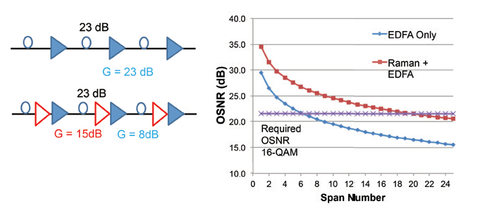
The following picture illustrates the effect of Raman amplification on a simple multispan link with 23 dB loss per span compensated by 23 dB of amplification. In one case, each span loss is compensated with an EDFA, while in the other case, the gain is divided between the distributed Raman amplifier and the EDFA. Inferring from the figure, it is clearly that with the hybrid EDFA/Raman amplification, the OSNR curve has shifted upwards towards higher OSNR values. This means the link can obtain higher OSNR for the same span number, or, the same OSNR for a much larger span number. By incorporating Raman amplifier into DWDM networks, the link becomes more robust, with more margin available for future repairs or changes along the link.
hybrid EDFA and Raman amplifier
Deployment Considerations for Raman Amplifier
It is undoubted that Raman amplifier can provide significant benefit to DWDM networks, what should be noticed here is that, there are also several key precautions to deploy Raman amplifier in real-life environment, which must be addressed so that the potential benefits can be fully realized.
Keep Fiber Clean
When deploying Raman amplifier in a DWDM system, the equipment needs to be connected to the network fiber with minimum connection loss. Since contamination like dust and dirt, or misalignment is detrimental to fiber attenuation, network operators must keep the fiber and connectors clean during the connection process, not degrade the performance of the system.
Connection Loss
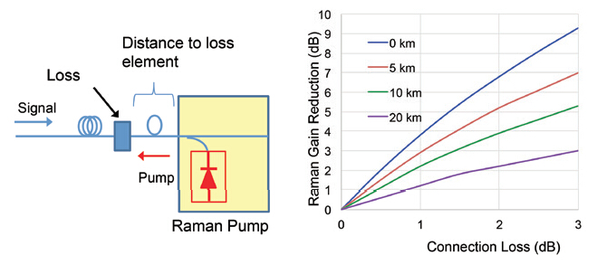
Connection loss could have a significant impact on the whole network. The following picture shows the reduction in Raman gain due to different connector losses when the connector is located very close to the Raman pump. The three curves correspond to different fiber attenuation levels at 1550 nm. In this example, a Raman amplifier with a net gain of 15 dB is involved, a 1 dB connection loss can result in a 4 dB gain reduction, and a 2dB connection loss increases the reduction in Raman gain to 7 dB.
impact of connection loss on Raman amplifier
Location of the Loss Element
The location of the loss element serves as a vital factor. The figure below shows the Raman gain reduction according to different position of the loss elements, at 0 km, 5 km, 10 km and 20 km away from the Raman pump. It reveals that the Raman gain reduction is lower if the connection loss is located further away from the Raman pump. This is because most of the Raman gain occurs close to the Raman pump. We can also conclude that most of the gain obtained through Raman amplification is obtained in the region of the effective length of the fiber, which is in the ~20km range.
location of loss elements with raman amplifier
Conclusion
Adoption of Raman amplifier significantly consolidates optical link while extends transmission reach in DWDM networks. Raman amplifier also serves as a good implementation of EDFAs, enabling applications which are not feasible or practical with conventional EDFA technology. Thus increasing the distance and capacity of long-haul DWDM systems.