Friday, March 31, 2017

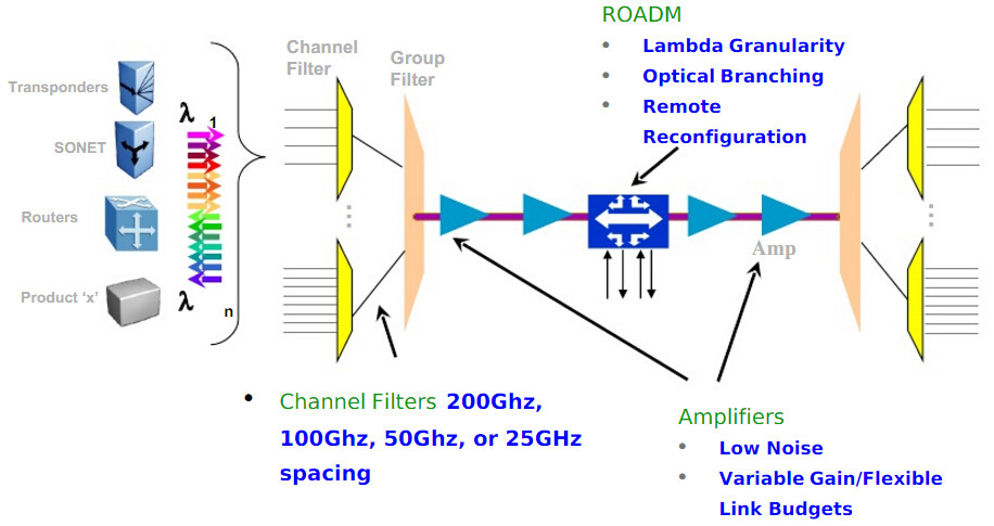
Optical Transponder (O-E-O) Used in WDM Network

WDM technology is commonly used in today’s optical network. It basically assigns each service (10G LAN, SONET/SDH, Fiber Channel, etc) an independent dedicated wavelength—which then is multiplexed into one single fiber. Eliminating the use of multiple fibers while increasing fiber capacity, WDM system is beneficial to both service providers and end users. Optical transponder, also referred to as O-E-O (optical-electrical-optical), serves as an integrated part of WDM system and it is critical for signal transmission in the whole system. This article will guide you through how optical transponder operates in a WDM network.
Basics of Optical Transponder (O-E-O)
The optical transponder (O-E-O) works as a re-generator which converts an optical input signal into electrical form, then generates a logical copy of an input signal and uses this signal to drive a transmitter to generate an optical signal at the new wavelength (optical-electrical-optical). Its most prominent feature is that it automatically receives, amplifies, and then re-transmits a signal on a different wavelength without altering the data/signal content. Clients can be electrical or optical (1310 or 1550 nm), co-located or some distance away. Line side interfaces can be fiber, CWDM or DWDM with a variety of reaches supported.
optical transponder (O-E-O)
Common Applications of Optical Transponder (O-E-O)
Optical transponder is widely accepted in WDM networking and many other applications. let’s go through some commonly used ones.
1. Multimode to single-mode conversion
Some optical transponders can convert from multimode to single-mode fiber, short reach to long reach lasers, and/or 850/1310 nm to 1550 nm wavelengths. Each optical transponder module is protocol transparent and operates fully independent of the adjacent channels.
multimode to single-mode conversion
2. Redundant fiber path
Each optical transponder module can also include a redundant fiber path option for extra protection. The redundant fiber option transmits the source signal over two different optical paths to two redundant receivers at the other end. If the primary path is lost, the backup receiver is switched on. Since this is done electronically, it is much faster and more reliable.
redundant fiber path
3. Repeater
As an optical repeater, some optical transponders effectively extend an optical signal to cover the desired distance. With the clock recovery option, a degraded signal can be dejittered and retransmitted to optimize signal quality.
Repeater
4. Mode Conversion
Mode conversion is one of the quickest and simplest ways of extending multimode optical signals over greater distances on signal-mode fiber optics. And most receivers are capable of receiving both multimode and single-mode optical signals.
mode conversion
5. Wavelength Conversion
Wavelength conversion in commercial networks today is only carried out by optical transponder. We know that optical network equipment with conventional fiber interfaces like LC, SC, ST, etc operates over legacy wavelength of 850 nm, 1310 nm, and 1550 nm. Which means they must be converted to CWDM or DWDM wavelength to fit in the system, and this is what WDM transponders used for—converse wavelength by automatically receiving, amplifying, and re-transmitting a signal on a different wavelength without altering the data/signal content. The following picture depicts the conversion process: a 10G switch (with signal output of 1310 nm) is to be linked to a CWDM Mux/Demux channel port (1610 nm). An optical transponder with a standard SMF SFP+ and a 1610nm CWDM SFP+ is adopted between the switch and CWDM Mux/Demux, thus the wavelength conversion is realized by the optical transponder.
wavelength conversion
Network Structure with Optical Transponder
Then how exactly optical transponder benefits your network system? Here we provide two possible configurations of network over WDM ring which deploys optical transponder.
For line network over a WDM ring
The line network consists basically of two point-to-point links between A-B and B-C, each requiring transponders at the endpoints. If node B fails, communication between A and C should still be possible, because B can be bypassed by the two adjacent optical transponders. For this the protection in/outputs of the transponders are connected by a bypass link. If node B fails, S1 in both transponders switch to the protection connection.
optical transponder in line network
For star network over a WDM ring
As for a star network over a WDM ring, where the nodes A, C and D are connected to the star node B. Node B has a backup node B’ for redundancy. Here the protection in/outputs of the transponders are used to connect the nodes A, C and D to node B’ if node B failed.
optical transponder in star network
Conclusion
Optical transponder holds a critical position in WDM networking system and cannot simply be underestimate. We have illustrated the functionality and applications of optical transponder, as well as presenting possible configurations of network over WDM rings. Hope that may help you to have a better understanding of the optical transponder.
Friday, March 24, 2017

How to Overcome the Challenges of Adopting WDM-PON in FTTx?

The bandwidth demand in the access network has been increasing rapidly over the past several years. Passive optical networks (PONs), as the most economical FTTx architecture that needs no power supply, have evolved to provide much higher bandwidth in the access network. A PON is a point-to-multipoint optical network, where an optical line terminal (OLT) at the central office (CO) is connected to many optical network units (ONUs) at remote nodes through one or multiple 1:N optical splitters. WDM-PON combines the virtues of point-to-point dedicated connections with the fiber efficiency and economics of PON, which is considered as a candidate solution for FTTx network. This article offers solutions for deploying WDM-PON in regard to its cost and technical challenges.
WDM-PON Technology Explanation
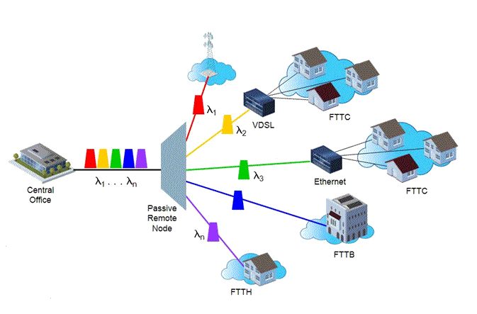
WDM-PON is the passive optical network (PON) based on wavelength division multiplexing (WDM) technology, which delivers higher network security. This system allows ONUs to have light sources at different tuned wavelengths coexisting in the same fiber, increasing the total network bandwidth and the number of users served in the optical access network. The CO contains multiple transceivers at different wavelengths with each output wavelength creating a dedicated path or channel for a particular user by passing through a wavelength selective/dependent element at the remote node (RN). Wavelength selection can also be achieved by filtering at the user. The upstream connection similarly utilizes a dedicated wavelength channel.
WDM-PON system
Why Apply WDM-PON in FTTx Networks?
We have known that WDM-PON supplies each subscriber with a wavelength instead of sharing wavelength among 32 or even more subscribers in TDM PON, thus providing higher bandwidth provisioning. WDM-PON is regarded as a candidate solution for next-generation PON systems in competition with TDM PON for possessing the following advantages:
  • WDM-PON allows each user being dedicated with one or more wavelengths, thus allowing each subscriber to access the full bandwidth accommodated by the wavelengths.
  • WDM-PON networks typically provide better security and scalability because each home only receives its own wavelength.
  • The MAC layer control in WDM-PON is more simplified as compared to TDM PON because WDM-PON provides P2P connections between the OLT and the ONU, and does not require the point-to-multipoint (P2MP) media access controllers found in other PON networks.
  • Wavelength in a WDM-PON network is effectively a P2P link, thus allowing each link to run at a different speed and with a different protocol for maximum flexibility and pay-as-you-grow upgrades.
WDM-PON Challenges: How to Deal with Them?
Despite these attractive features, there are also some demerits that hinder the implementation of WDM-PON networks.
  1. When implementing WDM-PON, one should apply wavelength routers or power splitters in the ONUs, and both of the methods need a colorless ONU.
  2. As for long reach WDM-PON system, the protection is necessary to ensure the network reliability and performance.
Concerning the challenges that remain in WDM-PON deployment, here we provide some solutions for your reference.
For Colorless ONU
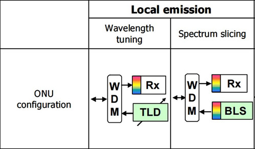
The ONUs in WDM-PON need to be colorless, which means no ONU is wavelength specific in order to reduce the costs of operation, administration, maintenance and production. Local emission is proposed to solve this problem. There basically exist two local emission approaches: wavelength tuning and spectrum slicing. The ONU of the wavelength tuning approach consists of a tunable laser diode (TLD) as a transmitter (Tx), an optical receiver (Rx) with wavelength selector (WS), and a WDM coupler that divides or combines the upstream and downstream signals. The configuration of the ONU in the spectrum slicing approach is similar to that of wavelength tuning approach, except that a broadband light source (BLS) with WS is used instead of the TLD.
colorless ONUs for WDM-PON
For Long-Reach Protection
As for long-reach network, protecting the feeder fiber that transmits data from potential damage is vital. Then how to achieve the protection? It is suggested to adopt 3-dB optical couplers, which can be used to split or combine the path of WDM signals to or from both the working and protection fibers in the OLT or in the wavelength router. Note that the OLT and the wavelength router are typically located in the central office (CO) and in the access node (AN) respectively. However, this protection method has a low loss budget because of the adoption of the 3-dB optical couplers. To this end, a wavelength-shifted protection scheme has been proposed, which is deploying the cyclic property of the 2×N athermal arrayed-waveguide grating (AWG) and two wavelength allocations for working and protection. In this case, 3-dB optical couplers are not needed.
Conclusion
WDM-PON is proving to be the most promising long-term, scalable solution for delivering high bandwidth to the end user. Meanwhile, advances in key device technologies had laid the foundation for realization of a high performance, low cost WDM based PON system. Thus, in competition with other high-speed access network technologies, WDM-PON is considered the most favorable for the required bandwidth in the near future.

Friday, March 17, 2017

How Does Erbium Doped Fiber Amplifier (EDFA) Benefit WDM Systems

Optical network that involves WDM (wavelength division multiplexing) currently gains in much popularity in existing telecom infrastructure. Which is expected to play a significant role in next generation networks to support various services with very different requirement. WDM technology, together with EDFA (Erbium Doped Fiber Amplifier), allowing the transmission of multiple channels over the same fiber, that makes it possible to transmit many terabits of data over distances from a few hundred kilometers to transoceanic distances, which satisfy the data capacity required for current and future communication networks. This article explains how can WDM system benefit from this technology.
Basics of EDFA
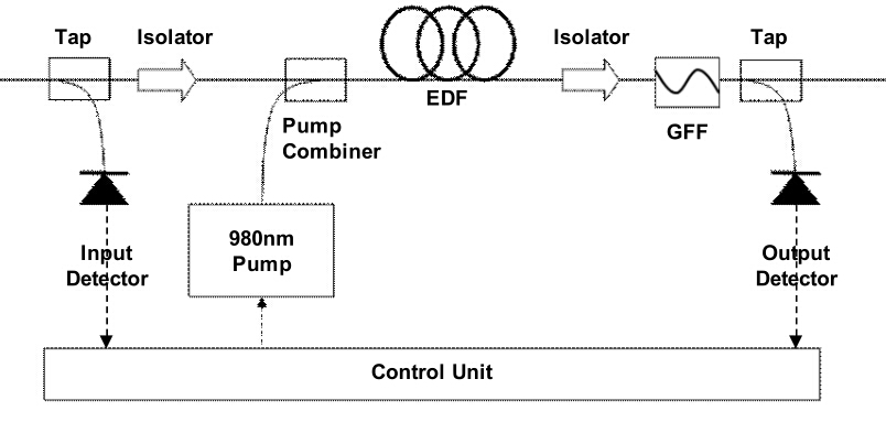
The key feature of EDFA technology is the Erbium Doped Fiber (EDF), which is a conventional silica fiber doped with erbium. Basically, EDFA consists of a length of EDF, a pump laser, and a WDM combiner. The WDM combiner is for combining the signal and pump wavelength, so that they can propagate simultaneously through the EDF. EDFA can be designed that pump energy propagates in the same direction as the signal (forward pumping), the opposite direction to the signal (backward pumping), or both direction together. The pump energy may either by 980nm pump energy or 1480nm pump energy, or a combination of both. The most common configuration is the forward pumping configuration using 980nm pump energy. Because this configuration takes advantage of the 980nm semiconductor pump laser diodes, which feature effective cost, reliability and low power consumption. Thus providing the best overall design in regard to performance and cost trade-offs.
basic EDFA design
Why EDFA Is Essential to WDM Systems?
We know that when transmitting over long distance, the signal is highly attenuated. Therefore it is essential to implement an optical signal amplification to restore the optical power budget. This is what EDFA commonly used for: it is designed to directly amplify any input optical signal, which hence eliminates the need to firstly transform it to an electronic signal. It simply can amplify all WDM channels together. Nowadays, EDFA rises as a preferable option for signal amplification method for WDM systems, owing to its low-noise and insensitive to signal polarization. Besides, EDFA deployment is relatively easier to realize compared with other signal amplification methods.
4-Channel WDM System With or Without EDFA: What Is the Difference?
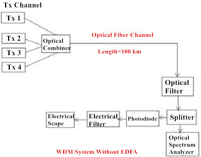
Two basic configurations of WDM systems come in two forms: WDM system with or without EDFA. Let’s first see the configuration of WDM system without using it. At the transmitter end, channels are combined in an optical combiner. And these combined multiple channels are transmitted over a single fiber. Then splitters are used to split the signal into two parts, one passes through the optical spectrum analyzer for signal’s analysis. And other passes through the photo detector to convert the optical signal into electrical. Then filter and electrical scope is used to observe the characteristics of signal. In this configuration signals at long distance get attenuated. While this problem can be overcome by using erbium doped fiber amplifier.
WDM system without EDFA
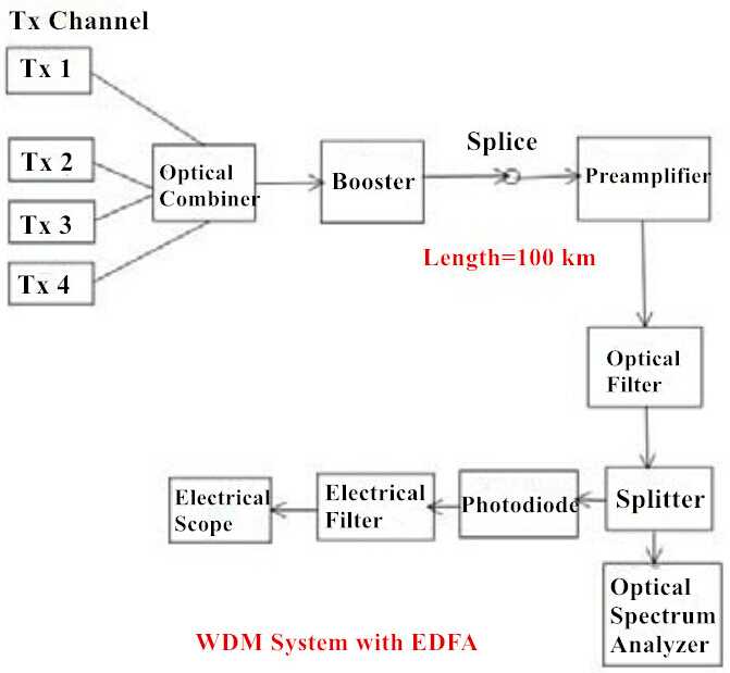
As for WDM system which uses EDFA, things are a little bit different. Although the configuration is almost the same as WDM system without it, some additional components are used. These components are EDFAs which are used as a booster and pre-amplifier, and another additional component is optical filter. With the adoption of optical amplifier, this system doesn’t suffer from losses and attenuation. Hence, it is possible to build broadband WDM EDFA which offer flat gain over a large dynamic gain range, low noise, high saturation output power and stable operation with excellent transient suppression. The combination provides reliable performance and relatively low cost, which makes EDFAs preferable in most applications of modern optical networks.
WDM system with EDFA
Conclusion
Among the various technologies available for optical amplifiers, EDFA technology proves to be the most advanced one that holds the dominate position in the market. In future, the WDM system integrated with high performance EDFA, as well as the demand for more bandwidth at lower costs have made optical networking an attractive solution for advanced networks.

Thursday, March 9, 2017

CWDM and DWDM for Metro Networks: How to Make it Economical?

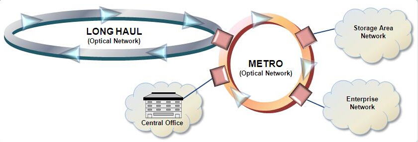
Fiber exhaust still appears to be a common problem faced by most metro (or metropolitan) networks. Although the cost of fiber optic cable is consistently dropping, the trenching, labor, and other installation costs towards optical fiber stay rather high. This may partially explain why an increasing number of metro networks incline to adopt WDM technology to enhance fiber capacity. It is known that WDM technology used in metro networks generally takes two forms: coarse WDM (CWDM) and dense WDM (DWDM). This article will deliver an overall comparison of CWDM and DWDM in metro networks, from the perspective of the roles each plays and the operating cost. Help you to decide how to reach an economical solution.
CWDM-DWDM-metro-network
CWDM vs. DWDM: Different Role in Metro Network
As for the major difference between the two WDM technology, their names imply it all: is the channel spacing within the window of the optical spectrum (see the picture below). CWDM has a wider pass-band that spaced at 20 nm apart, which allows for the use of less expensive components like uncooled lasers and thin-film filter technology. The cost advantage of CWDM makes it a more appropriate alternative for the shorter distance typically found in metro access networks.
CWDM
However, metro networks sometimes demand for longer distance and more wavelengths that CWDM simply cannot satisfy, then DWDM with its narrow channel spacing (0.8 nm) should be put into use. The problem is that the components related to the latter are too expensive for some edge networks. In this case, the best solution is to combine both CWDM and DWDM in metro area networks.
DWDM
CWDM in the Metro Access
CWDM nowadays commonly supports at least eight of the eighteen ITU-T G.694.2 defined channels over distances of up to 80 km. With simple point-to-point and ring network topology, CWDM eliminates the need for erbium doped-fiber amplifier (EDFA) typically associated with DWDM. CWDM's lower cost and small footprint fit well with customer premises and co-location installations. And due to the readily available of Gigabit interface converters and small form factor pluggable (SFP) transceivers for CWDM platform, it gains in much popularity in enterprise and storage networks. CWDM is most fit in networks with the following features:
  • Low channel count of 4 to 8 channels
  • Transmission rates of <2.5 Gbits/sec per channel, and short distances of <80 km
DWDM in the Metro Core
Carriers are consistently looking for a cheaper and simpler version of long-haul DWDM, which drives the equipment suppliers to adapt DWDM systems accordingly. Banded wavelength filters, elimination of dispersion compensation, and more tolerant channel spacing were seen as ways to accomplish this goal. Nowadays, DWDM is well suited to high-capacity core networks in the metro, and to regional extensions between metro areas.
Cost Concerning CWDM and DWDM
The cost is still presented as a key difference in metro network systems. DWDM lasers are generally more expensive than those applied in CWDM system, the cooled DFB lasers offer cost-effective solutions for high-capacity large metro rings. And the cost of the this system is amortized over the large number of customers served by the systems. Whereas for metro access networks that demand for lower-cost and lower-capacity systems, it heavily depends on what the customer is willing to pay for broadband service. Since a metro access application would have fewer wavelengths, so based on equipment cost, CWDM is a more profitable solution for metro access points where cost is more important than capacity.
The Future of CWDM and DWDM in Metro Network
Some vendors offering both CWDM and DWDM technologies have merged the system building blocks onto a single platform. This approach allows the de-multiplexed CWDM traffic to be directly connected to DWDM transponders, saving equipment and space. It also enables end-to-end performance monitoring and cost optimization throughout the entire metro network. Then there is no need to choose between these two WDM technologies. The better choice is an integrated solution that makes use of the economies of CWDM for shorter distances, and provides the power of a DWDM network where longer distances and more capacity are needed. The result is an integrated, economical network that doesn't require a carrier to compromise on quality, quantity, or cost. The DWDM building blocks are shown below.
DWDM building blocks
Conclusion
From what we have discussed in this article, we can conclude that metro networks will benefit from the mixture of CWDM and DWDM systems. And metro networks are becoming more flexible over this converged solution: with CWDM fitting the needs of today, and DWDM for the growing demand for increased coverage in the future. Take advantage of both the coarse and dense WDM technology, this integrated metro network that delivers much reliability and flexibility is the trend of the future.