Tuesday, February 28, 2017

Comparison Between CFP-100G-SR10 and CFP-100G-LR4 Module

Although 10/40G Ethernet nowadays still captures the major position in the world of telecommunication, service providers and enterprise data centers are actually undertaking a transformation of infrastructures. Which fuels the demand for higher speeds, greater scalability, and better performance and reliability, making migration to 100G network an inevitable trend. Optical transceiver modules always pertain to an integral part of overall system design, as for 100G CFP modules, the options vary widely. This article makes a comparison of the most commonly two: CFP-100G-SR10 and CFP-100G-LR4 transceiver module.
Basics of 100G CFP Transceiver Module
CFP transceiver module is a hot pluggable form factor designed for optical networking applications. CFP the acronym from 100G (here C equals 100 in Roman numerals) form factor pluggable. The name clearly indicates that CFP transceiver module is introduced typically for 100G interfaces. To make it easier to understand, let’s begin with general CFP architecture. It basically consists of two parts—electrical interface interacting with equipment, and line card interface and optical line interface.
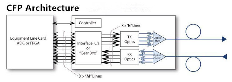
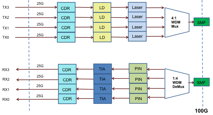
100G CFP architecture
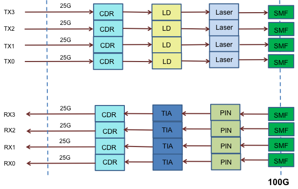
From equipment line card to electrical interface, CFP has several “M-Lines” with 10Gbps speed. If CFP is working 100GBase-LR4 mode, then it has 10 x 10Gbps M-Lines. As for 40GBase-LR4, it uses 4 x 10Gbps M-Lines. The so called “gear box”is electrical 10:4 mux/demux module aggregating up to 10 M-Line interfaces in maximum 4 N-Line interfaces. Each N-Line is 25Gbps for 100GBase-LR4 and 10Gbps for 40GBase-LR4. The N-Line is converted to optical signal with different wavelength and all four wavelengths are transmitted to CFP line interface using built in passive optical multiplexers.
CFP-100G-SR10 and CFP-100G-LR4 Overview
100G CFP modules offer connectivity options for a wide range of service provider transport, data center networking, and enterprise core aggregation applications. The basic information of CFP-100G-SR10 and CFP-100G-LR4 module is provided below.
CFP-100G-SR10 Module
CFP-100G-SR10 is an IEEE standardized CFP module supporting link lengths of 100 m and 150 m respectively on laser-optimized OM3 and OM4 multifiber cables. It primarily enables high-bandwidth 100-gigabit links over 24-fiber ribbon cables terminated with MPO/MTP-24 connectors. It can also be used in 10 x 10 Gigabit Ethernet mode along with ribbon to duplex fiber breakout cables for connectivity to ten 10GBASE-SR optical interfaces. CFP-100G-SR10 interface serves as a more cost-effective solution, which is optimized for data center application and is limited to short distances.
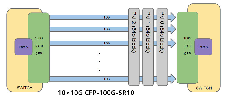
CFP-100G-SR10
CFP-100G-LR4 Module
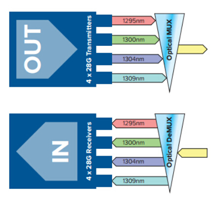
CFP-100G-LR4 is standardized by IEEE using standard LC dual fiber interface with single-mode cable, but running four optical wavelengths each direction (1295.56 nm, 1300.05 nm,1304.59 nm, 1309.14 nm) and muxing/demuxing of these wavelengths happening inside CFP module. Each wavelength is running at 25.78 Gbps and it is possible to achieve up to 10 km. Compared to CFP-100G-SR10, CFP-100G-LR4 delivers much better reach for long-haul applications, but at a cost premium.
Comparison Between CFP-100G-SR10 and CFP-100G-LR4
In this section, we’re trying to figure out the difference between CFP-100G-SR10 and CFP-100G-LR4 from the perspective of connectors and cabling used on each. For connectors, 24-fiber MPO/MTP connector is for CFP-100G-SR10 module while dual SC/PC connector for CFP-100G-LR4. Note that only patch cords with PC or UPC connectors are supported. The cabling specification and features for CFP-100G-SR10 and CFP-100G-LR4 are presented in the following diagrams.

Service providers and data centers are embracing the trend of 100G network migrations, IT managers and network designers must think twice when choosing from those various 100G transceiver options. CFP-100G-SR10 is preferred due to lower cost over LR4, but its reaching distance is limited. Whereas CFP-100G-LR4 enables data transmission up to 10 km with higher price. This article generally offers some basic knowledge of CFP-100G-SR10 and CFP-100G-LR4 transceiver modules, the decision actually depends on your specific demands and requirements of your applications. Always be aware of what you need, which will work best for you.

Sourcehttp://www.fiber-optic-solutions.com/cfp-100g-sr10-cfp-100g-lr4-comparison.html

Friday, February 17, 2017

QSFP28 Transceiver: Making the Switch to 100G Network

As data centers around the world explore their options for increasing network speeds and bandwidth, 10G has been a traditional favorite, and 40G is not able to keep pace with the requirements. In this case, 100G network appears to be a preferable option to accelerate data flow for those bandwidth-hungry applications. QSFP28 transceiver module hence becomes the universal data center form factor for 100G optical transmission. This article will address the necessity of 100G network, while illustrating QSFP28 transceiver modules used in 100G transmission.
100G: The Optical Revolution in Data Centers
The 100G adoption rate in optical landscape is consistently on the rise for the past few years. It is predicted that over half of the data center optical transceiver transmission will make the shift to 100G. The traditional 10G or even 40G may not be enough considering the explosion of data, therefore, 100G is going to become the new standard, and it has the following advantages.
100G optical transmission vs. 40G optical transmission
Cost Efficiency—100G now delivers a compelling price point, offering far greater capacity increases for the cost. And it still future-proofing the network with unsurpassed bandwidth.
Proactive Scale—100G offers the expansion and scalability to support the reliability, manageability and flexibility demanded of modern networks while preparing data centers for future bandwidth and speed requirements.
Speed and Capacity—10GG optical transport will not be enough for data intensive industries. Thus 100G is specifically designed to transport enormous amounts of data with ultra-low latency.
Flexibility—100G will be the preferred technology across long-haul networks. 100G networking can be customized, optimized, and easily expanded to allow for changes in the future.
Cost Decrease—The market transition to 100GE is now in full force. The growth in 100G deployments will undoubtedly drive down the cost of 100G transceiver modules.
100G QSFP28 Transceiver Unravel
QSFP28 transceiver generally has the exact same footprint and faceplate density as 40G QSFP+ . Just as the 40G QSFP+ is implemented using four 10Gbps lanes, the 100G QSFP28 transceiver is implemented with four 25-Gbps lanes. With an upgrade electrical interface, QSFP28 transceiver is capable of supporting signal up to 28Gbps signals. Though QSFP28 transceiver keeps all of the physical dimensions of its predecessors, it surpasses them with the strong ability to increase density, decrease power consumption, and decrease price per bit. The Following are some QSFP28 transceivers for different applications.
100G QSFP28 transceiver
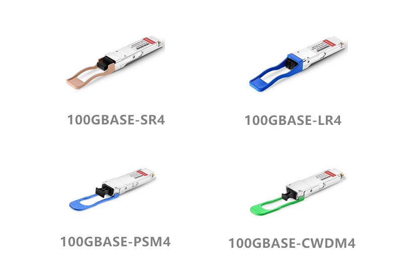
QSFP28 100GBASE-SR4
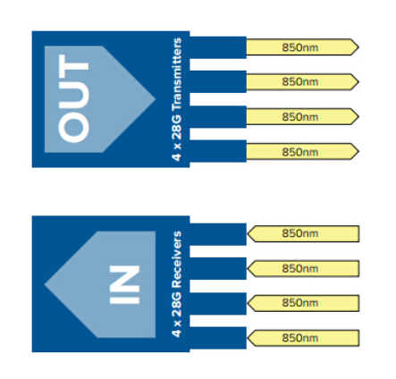
100G QSFP28-SR4 came out firstly to support short distance transmission via multimode fiber. This transceiver module can support 100G transmission up to 70m on OM3 MMF and 100m on OM4 MMF. With MTP interface, the 100G QSFP28-SR4 module enables 4×25G dual way transmission over 8 fibers.
QSFP28 100GBASE-SR4
QSFP28 100GBASE-LR4
100G QSFP28-LR4 is specifically designed for long distance transmission. The module utilizes WDM technology for 4×25G data transmission, and these four 25G optical signals are transmitted over four different wavelengths. With a duplex LC interface, the 100G QSFP28-LR4 module enables 100G dual-way transmission up to 10 km over single-mode fiber.
QSFP28 100GBASE-LR4
QSFP28 100GBAS-PSM4
PSM4 uses four parallel fibers (lanes) operating in each direction, with each lane carrying a 25G optical transmission. It sends the signal down to eight-fiber cable with an MTP interface. The operating distance of 100G QSFP28-PSM4 is limited to 500 m.
QSFP28 100GBASE-PSM4
QSFP28 100GBASE-DWDM4
DWDM4 uses WDM technology—an optical multiplexer and de-multiplexer to reduce the number of fibers to 2. It can operate on single-mode fiber up to 2 km over duplex LC interface. Compared with QSFP28-LR4, it has shorter transmission distance and lower cost.
QSFP28 100GBASE-DWDM4
100G QSFP28 Cables
In addition to the QSFP28 transceiver modules mentioned above, cables can also be deployed in 100G transmission. The cables can be either direct-attach copper cables (DACs), or active optical cables (AOCs). QSFP28 DACs offer the lowest cost but are limited in reach to about 3 m. They are typically used within the racks of the data center, or as chassis-to-chassis interconnect in large switch and routers. QSFP28 AOCs are much lighter and offer longer reach up to 100 m and more.
Frequently Asked Questions About QSFP28 Transceiver
What Is the Difference Between QSFP28 Transceiver and QSFP+?
These two have the same size form factor and the number of ports, however the lane speeds of QSFP28 transceiver are increased from 10 Gbps to 25 Gbps. The increase in density is even more dramatic when compared to other 100Gbps form factors: 450% versus the CFP2.
How Many QSFP28 Transceiver Moduels Can Fit into One Switch?
With QSFP28 transceiver, a one rack-unit (RU) switch can accommodate up to 36 QSFP28 ports. While many more varieties of transceivers and cables (DACs and AOCs) can plug into these ports.
Conclusion
100G QSFP28 transceiver offers direct compatibility with your existing switches and routers, and it facilitates the process of scaling to 100G networks with the simplicity as 10G networks. With higher port density, lower power consumption and lower cost, QSFP28 transceiver is an ideal alternative for large scale data centers, as well as future network expansions. All the QSFP28 transceiver modules presented in this article are available at FS.COM. For more details, please visit www.fs.com.

Friday, February 10, 2017

Fiber Patch Cable Cleaning Recommendations

Fiber optics have expanded the capabilities and possibilities of networks beyond our expectation. Fiber patch cable serves as a common yet indispensable part which determines connection quality between fiber optic equipment, therefore it has no tolerance to any contaminant like dust and dirt. So keeping the end face of patch cables clean to ensure performance and reliability of the network is vital. This article offers general tips on patch cable cleaning, while introduces some professional tools that help simplify the process.
Why Is Patch Cable Cleaning Critical?
It is claimed that over 85% of fiber related problems in data centers, campus, and other enterprise or telecom environments are caused by contaminated connectors or end-faces. Which can often lead to degraded performance, or even worse, failure of the whole network system. So, cleaning consideration is always put in a paramount place in optical network transmission.
To ensure proper performance and reliability, care must be taken with the installation and maintenance of patch cable end face, as well as the removable fiber connectors. Because data are transmitted through the small core of the fiber patch cable, a very small amount of dirt or residue may significantly increase the connector’s attenuation and weaken the signal. Lack of applying proper patch cable cleaning procedures can directly impact the quality of the system’s performance.
General Tips for Patch Cable Cleaning
fiber patch cable cleaning is one of the most rudimentary and essential procedures to ensure network availability and reliability. The following lists some general suggestions when performing patch cable cleaning.
Point 1: Try to work in a clean area. Avoid working around heating outlets.
Point 2: Always keep dust caps on connectors and bulkhead adapters for as long as possible. Only remove the dust caps to clean the components prior to making a connection.
Point 3: Never touch the ferrule end face of a fiber optic connector. No matter what you do, you will leave contamination behind.
Point 4: Always clean connectors before inserting into an adapter. Use specialized cleaning tools or lint free pads and isopropyl alcohol to clean.
Point 5: Ferrules on the connectors/cables used for testing will get dirty by transference of contaminants from alignment sleeves in the bulkhead adapters, so test cables and adapters should be cleaned or replaced regularly when testing a large system.
Recommendations of Efficient Patch Cable Cleaning Tools
It is important to have proper tools to facilitate fiber patch cable cleaning job, which will greatly minimize the cleaning time and difficulty, making the cleaning process easier and more efficient. The commonly used patch cable cleaning tools are illustrated as follow.
aPush-type cleaners (one-clike cleaners): this pen-shaped push-type cleaners feature an easy one-push action, which quickly and effectively cleans the end face of connectors on patch cables or through adapters without any alcohol or harsh chemicals. Always select the cleaner model for the connector type to be cleaned, 2.5mm for SC, FC and ST, and 1.25mm for LC and MU.
bOne-clike MTP/MPO cleaner: this cleaner is specifically designed to clean MTP/MPO connector end face on patch cables or in adapters. The unique design enables effective cleaning of either male (with pins) or female (without pins) connector, in fiber breakout modules and even networking gear like switches and routers.
one-click mtp mpo cleaner
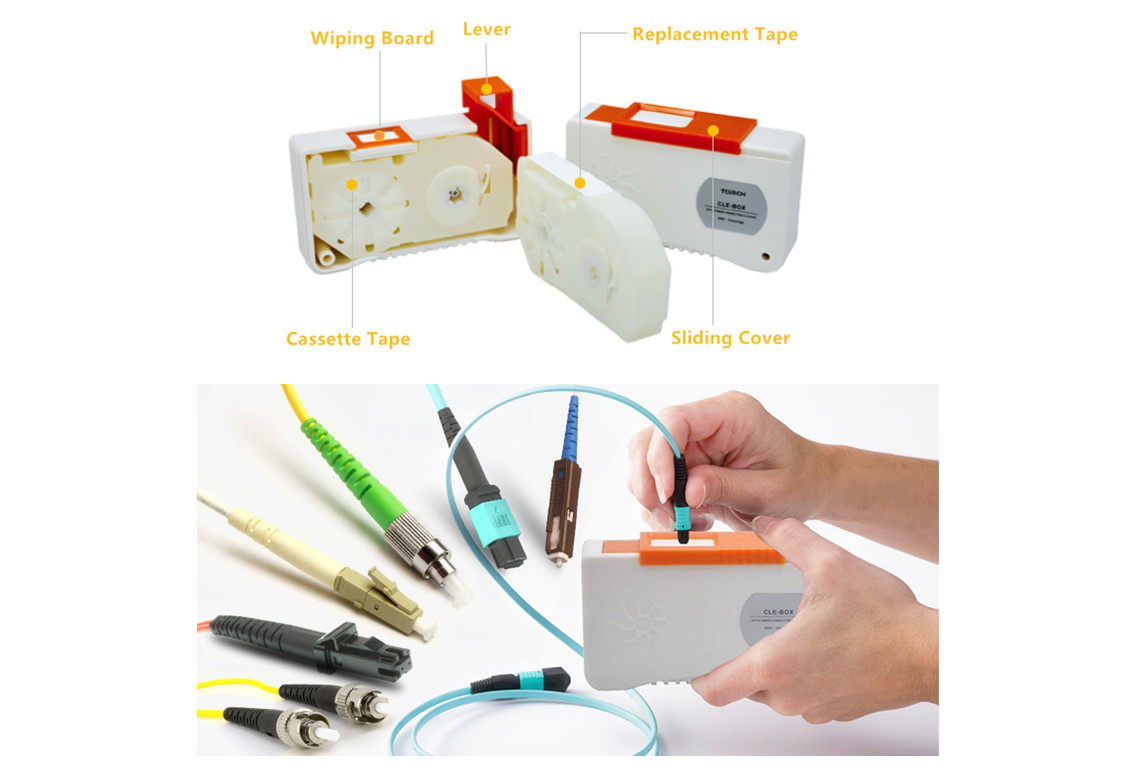
cReel-type cleaners (cassette cleaners): they typically contain a lint free reel of cloth that is moved after each cleaning, always presenting a clean surface. Reel-type cleaners are safe patch cable cleaning options without the need for alcohol. Besides, they have refillable cleaning tapes, making them ideal for lab, assembly lines and field use.
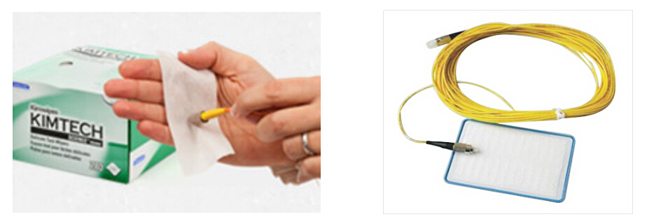
dWipes and cleaning cards: there are a wide variety of patch cable cleaning wipes and cleaning cards for both field and manufacturing applications. They can be used either dry or with cleaning fluid to remove common contaminants for effective patch cable cleaning.
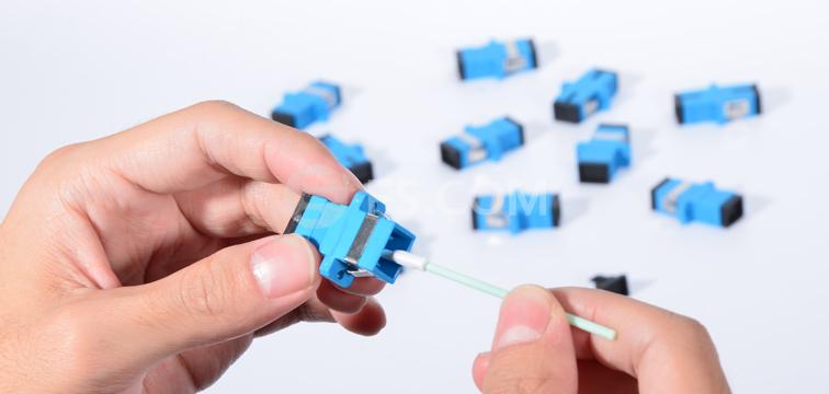
eCleaning swabs & sticks: Precisely designed, the mini foam clean swabs are made to serve various different patch cable cleaning and maintenance needs. Foam swabs are ideal for more precision cleaning where linting needs should be avoided. Swabs assist in cleaning small or hard to reach items.
fiber patch cable cleaning swab
Conclusion
For best optical performance, it is imperative that all fiber patch cable connections are clean and free of contaminants. An easy to use patch cable cleaning tool becomes a necessity for fiber technicians and installers. Even without specific training, field technicians and fiber installers can use a simple insertion and push motion to remove residue, debris and dust that can negatively impact network performance. So why not grab a patch cable cleaning tool to make your job easier?

Wednesday, February 8, 2017

How to Integrate PoE to Your Network?

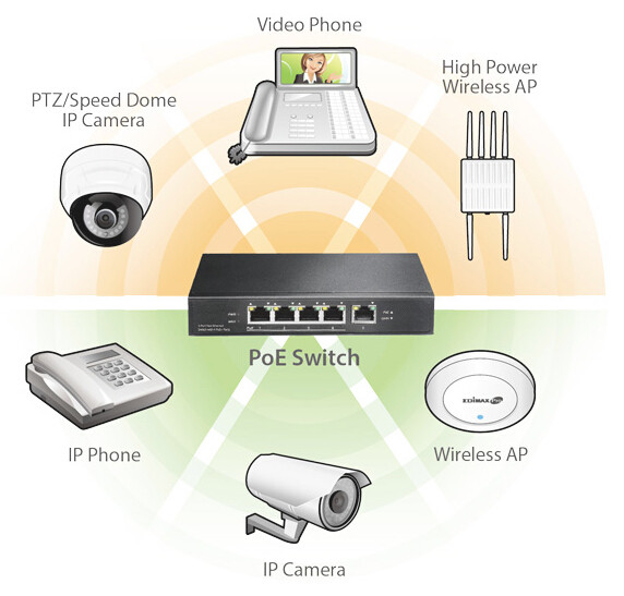
You may come across the situation when it is needed to install IP telephones, wireless access points or IP cameras to somewhere AC power outlets are not available. What would you do then? As extra power supply and wiring installation can be labor-intensified and time-consuming. The most feasible solution is to deploy PoE (Power over Ethernet)—a system standardized by IEEE802.3 that supplies low voltage power to Ethernet-enabled devices via the communication line. Here we illustrate how to upgrade your existing network to PoE.
PoE Network Explained
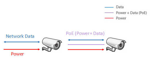
As its name suggests, PoE (power over Ethernet) is the technology to supply power directly via data cable, eliminating the need for additional electrical wiring. It makes network planning flexible and independent of switch sockets and cabinets, requiring no extra costs for excess wiring. Thus devices can be installed wherever structured Ethernet wiring is located, without the need for AC power outlets nearby.
PoE-power over ethernet network
Generally speaking, this technology enables network cables carry electrical power. Let’s take surveillance camera for example: it typically requires two connections when it is installed: a network connection to communicate with video recording and display equipment, and a power connection to deliver the electrical power to operate the camera. However, if this surveillance camera is PoE compatible, all we need is the network connection, as it can receive the needed electrical power from the cable as well.
PoE IP Camera
Advantages of PoE Network
We know that powered devices such as surveillance cameras and wireless access points are often located in places where traditional power outlets are difficult to install or even not available. Under such circumstances, PoE functions to facilitate the use of wireless access devices, IP phones, surveillance cameras, the benefits of which is thus obvious.
The advantages of power of Ethernet features that Ethernet is always ubiquitous, hence it greatly increases mobility for end devices. And as no AC power involved, PoE is safer to use. Moreover, it simplifies installation and operation without the need for extra AC power wiring, keeping the cabling secure while not interfering with the network operation. This makes power over Ethernet a much securer, more reliable and cost-saving solution.
How to Integrate PoE to Your Network?
Before upgrading your existing network to PoE-enabled one. You’d better firstly make clear that there are two types of devices involved in this system: power sourcing equipment (PSE) and powered devices (PD). PD refers to a power over Ethernet compatible network end device equipped to accept power transmitted over structured Ethernet cabling. PSE provides DC power to PD. A PSE may be an endspan device or a midspan device. An endspan device typically is a network switch enabled to provide PoE power on each port. A midspan device is connected in-line to each end device and adds power to the line.
There generally exist three routes to achieve power over Ethernet to your network.
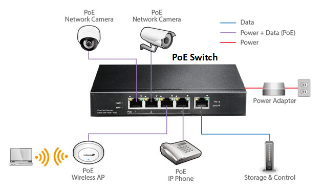
1. By PoE switch: a PoE switch is a network switch that with built-in power over Ethernet injection. Simply by connecting other network devices to the switch as normal, the switch will detect whether they are compatible to power over Ethernet and then enable power automatically. This kind of switches are available to suit all applications, from low-cost unmanaged edge switches with a few ports, up to complex multi-port rack-mounted units with sophisticated management.
PoE switch
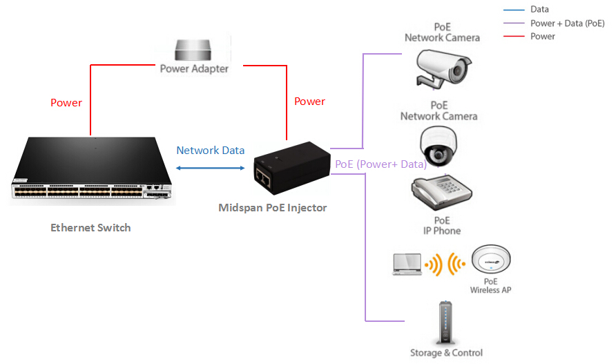
2. Using midspan: a midspan enables PoE capability to regular network switches. With midspan, one can upgrade existing LAN installations to PoE. Midspan also provides a versatile solution where fewer ports are required. Upgrading each network connection to power over Ethernet is as simple as patching it through the midspan.
PoE midspan injector
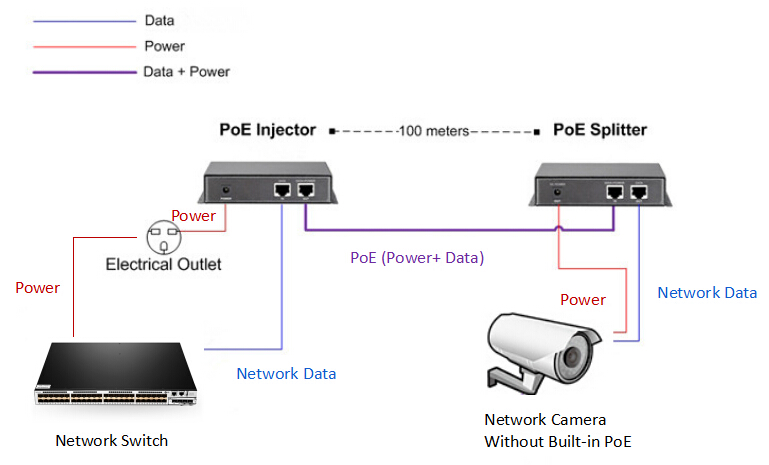
3. Via a PoE splitter: it is also feasible to upgrade powered devices (PDs) to power over Ethernet enabled ones by splitter. This splitter is patched into the camera’s network connection, and taps off the PoE power, which it converts into a lower voltage suitable for the camera.
PoE splitter
Conclusion
The simplicity of combining signal and power in one Ethernet cable connection makes PoE technology an ideal solution for enterprise network. In this case, PSE can provide power to a wide variety of PD in areas with no access to AC power. Deploying this technology in your network will lead to a safe, reliable, and economical way to deliver consistent and dependable power to common networking devices.

Saturday, February 4, 2017

Advice on Server Rack Cable Management

The proliferation of the cloud network and virtualization has brought higher network demands, which means data centers and network closets need to house and support an abundance of power and data cables. It is obvious that fail to deliver proficient cable management within a server rack can be devastated, either for network efficiency and performance, or for the overall look of the data center. The biggest challenge therefore is server rack cable management. This article intends to guide you through the process of achieving effective server rack cable management.
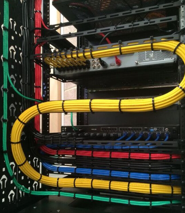
rack cable management
Benefits of Server Rack Cable Management
Here comes a frequently asked question: what exactly can data center operators benefit from valid rack cable management? The aspects listed below may explain.
Improved system performance: rack cable management incline to separate power and data cables within the racks, which greatly decrease the chance for crosstalk and interference between power and data cables.
Enhanced availability: mess of cable sometimes may confuse data center operators, resulting in human error that leads to an assortment of problems to the overall system. Effective rack cable management allows easier cable and IT device management, yet to reduce human error.
Improved maintenance and serviceability: effective rack cable management also ensures easier and safer access to individual components.
Increased cooling efficiency: by allowing hot exhaust air to escape out the back of the rack, cable management keeps cables organized and out of critical airflow paths.
Improved scalability: rack cable management simplifies moves, adds, and changes, making it easier to integrate additional racks and components for future growth.
Steps for Achieving Server Rack Cable Management
Then, we have made clear the importance and advantage of rack cable management. But how to achieve a well-organized and aesthetic appealing data center? We offer this seven-step guide for successful rack cable management.
Step One: Plan appropriately. Planning serves as the very primary stage for power and data cable management in server racks. An appropriate planning contributes to deliver smooth rack cable management process. Consulting a professional cabling contractor can be beneficial to complete the entire project.
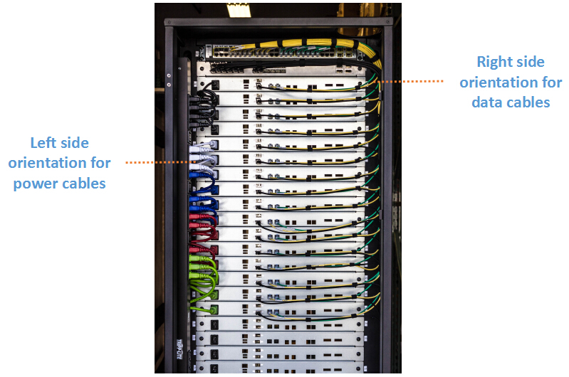
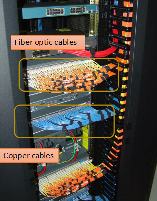
Step Two: Determine the routes for power cables and data cables. First to consider if the power and data cabling will enter from the top or bottom of the rack. Then, determine the routes to separate power and data cables, and copper data cables and fiber. This helps to prevent erratic or interference from degrading the performance of the system.
separate power cable and data cableseparate fiber and copper cable
Step Three: Identify cables. Good cable identification and administration are investments in infrastructure. Implement best practices like using colored cables as well as labeling cables to ensure easier cable identification, which contributes a lot to rack cable management.
labeling cable for cable management in rack
Step Four: Route and retain cables. Cables must be protected at points where they might rub or contact with sharp edges or heated areas. Rack cable management accessories like flexible cable tie and cable management arms can be used to route and retain cables.
Step Five: Secure cables and connectors. Cables and connectors should be secured to prevent excessive movement and to provide strain relief of critical points.
Step Six: Avoid thermal issues. Ensure the airflow path is rather important, since restrained airflow can cause temperatures rise. Sustained higher temperatures can shorten devices’ expected lifespan and lead to unexpected failures, resulting in unscheduled system downtime.
Step Seven: Document and maintain organization. Documenting the complete infrastructure including diagrams, cable types, patching information, and cable counts is important for future cable management. IT managers should commit to constructing standard procedures and verifying that they are carried out.
Conclusion
Effective rack cable management helps to improve physical appearance, cable traceability, airflow, cooling efficiency and troubleshooting time while eliminates the chance for human error. Meanwhile, power and data cable management within server racks also ensures the health and longevity of your cables. Hope what we discussed in the article is informative enough.

Pre-Terminated Cabling System Pros and Cons

The past few years have seen the steady rise in the use of pre-terminated cabling system. This cabling solution is considered as the norm for some key areas, such as data centers and commercial office fit-outs. Then, what is pre-terminated cabling system in essence? And what we can expect from this cabling alternative? This article intends to clear the confusion about pre-terminated cabling system, by analyzing its definition as well as explaining the benefits and drawbacks of it.
pre-terminated cabling system
What Is Pre-terminated Cabling System?
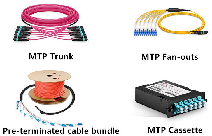
Pre-terminated systems are factory manufactured cables and modular components with connectors already attached, which usually have been tested, qualified and ready to plug and play in the network. They are available in both fiber and copper cabling. Pre-terminated systems offer unsurpassed advantages over conventional field installed system, which partially explains why the use of factory pre-terminated assemblies continues to grow, especially for data centers. Pre-terminated assemblies come in various forms, from trunk cablesconnectorized fan-outs, attached or discreet cassette modules to cable bundles with protective pulling grips installed over the connectors at one end.
pre-terminated assemblies
Where to Use Pre-terminated Cabling System?
At the beginning of the article, we’ve mentioned that pre-terminated cabling system commonly found its position in two fields: data centers and open offices. In response to the accelerated network capacity and application processing demands, data centers are expanding dramatically both in number and size. Which propel the advancement of alternative to improve the connectivity installation times and simplify the deployment for reliable and rugged cabling systems. The open office also benefits from the pre-terminated cabling system which can be quickly reconfigured to match the moves, adds and changes. Pre-terminated cabling system is expected to spread its influence in these types of scenarios.
pre-terminated cabling for data center and office
Pros and Cons of Pre-terminated Cabling System
We all know that one size does not fit all, so there are some serious pros and cons one must take heed of when dealing with pre-terminated cabling system.
Benefits of Pre-terminated Cabling System
Once used properly, pre-terminated solutions can bring a raft of benefits to cable installers and end-users.
Cost Saving: Although pre-terminated assemblies may have a higher initial cost since they include the factory termination time, the savings it provides go beyond the expense.
Time Saving: Pre-terminated system helps to save time in various ways. Since the assemblies are factory terminated, they require minimal engineering or assembly work on site. Meanwhile, pre-terminated assemblies also save testing and troubleshooting time. Also, pre-terminated assemblies are factory terminated which reduce many of the problems that may occur with field terminations.
Labor Saving: With pre-terminated assemblies, you don’t need as many on-site engineers pulling cables in and terminating them. As the pre-terminated links have been pre-tested, this vastly mitigates the need for troubleshooting and retesting.
Space Saving: For any data centers, the available space is always precious. Data center managers will embrace anything that contributes to promoting space utilization. With massive optical fibers being adopted in the data center to speed data transmission, pre-terminated assemblies offer much higher density and flexibility for data center upgrades.
pre-terminated cabling for high density data center
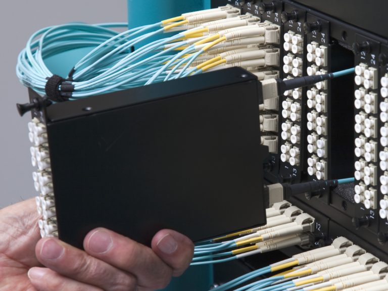
Cooling Advantages: Heating and cooling issues matter significantly especially in high density network environment. Pre-terminated cabling system allows much more flexibility in configuration for installers working in compact space. Optimized airflow can be achieved by using pre-terminated assemblies such as trunk cables and plug and play cassettes, in conjunction with high density frames.
Security Benefits: Security is always put in a paramount place in data centers. And pre-terminated cabling system does offer numerous security benefits. With pre-terminated solution, less manpower is required for the installation, making it simpler to manage “contract personnel”. While less specialist skills required to install pre-terminated assemblies, enterprises can even use their own team to do the job.
Drawbacks of Pre-terminated Cabling System
For all its advantages, pre-terminated cabling system is something of a double-edged sword, which means it certainly has some downsides. One drawback concerning pre-terminated cabling solution is the accuracy measurement required. Three is no turning up with cable assemblies that are too short or excessively long, and there is no containment space to store the excess cables. So accurate site surveys are rather essential.
Conclusion
With the benefits absolutely outweigh the drawbacks, pre-terminated cabling system provides an increasingly popular way of delivering a project in a more timely and cost effective manner. However, one should always carry out a comprehensive planning and site survey before installation to assure you can exactly benefit from pre-terminated cabling solution.

How to Use WDM for Fiber Capacity Expansion?

Imagine turning a cottage into a majestic skyscraper without having to deliver any innovation or construction. This is what wavelength division multiplexing (WDM) allows with your existing fiber optic network. The hunger for bandwidth propels service providers to make a substantial investment in upgrading fiber cabling infrastructure. This can be a challenge both economically and practically. However, the WDM technology offers an alternative to increase capacity on the fiber links that are already in place. Without deploying additional optical fiber, WDM greatly reduces the cost of network expansion.
WDM Technology Explanation
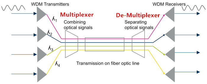
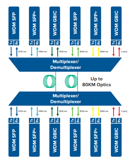
Let’s begin with the most fundamental question: What is WDM technology? Short for wavelength division multiplexing, WDM is a way of transmitting multiple simultaneous data streams over the same fiber. Since this happens simultaneously, WDM does not impact transmission speed, latency or bandwidth. WDM functions as multiplexing multiple optical signals on a single fiber by using different wavelengths, or colors, of laser light to carry different signals. Network managers can thus realize a multiplication effect in their available fiber’s capacity with WDM.
WDM-technology
To implement WDM to the infrastructure is rather simple, WDM setup generally consists of the following:
  • WDM transmit devices, each operating at a different wavelength
  • Multiplexer, a passive device that combines the different light sources into a blended one
  • Fiber infrastructure
  • De- Multiplexer, a passive device that splits the blended light source into separate ones
  • WDM receive devices
WDM-network-application
What Capacity Increase Can We Expect?
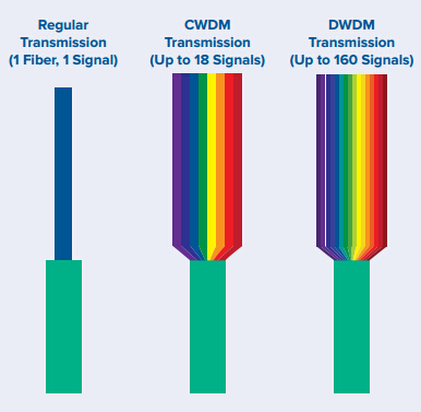
There are two variants of WDM: CWDM (coarse wave-division multiplexing) and DWDM (dense wave-division multiplexing). The only difference between them is the band in which they operate, and the spacing of the wavelengths and thus the number of wavelength or channels that can be used.
When using WDM on existing fiber cabling, you should also consider the fiber type (single-mode or multimode) and loss level. For CWDM, 8 to 18 devices may be possible, whereas for DWDM, up to 40 channels are the most common case, but it is possible to reach up to 160 channels.
use-WDM-increase-fiber-network-capacity
Choose the Right Type of WDM
We’ve known that both CWDM and DWDM are available to optimize network capacity. Then, here comes another question: should I choose CWDM or DWDM technology? Let’s make a comparison of them.
Coarse Wave Division Multiplexing (CWDM)
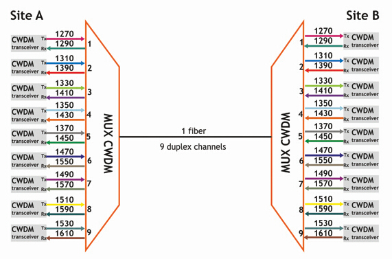
CWDM increases fiber capacity in either 4, 8, or 18 channel increments. By increasing the channel spacing between wavelengths on the fiber, CWDM allows for a simple and affordable method of carrying up to 18 channels on a single fiber. CWDM channels each consume 20 nm of space and together use up most of the single-mode operating range.
CWDM-mux-demux-function
Benefits of CWDM:
  • Passive equipment that uses no electrical power
  • No configuration is necessary, much lower cost per channel than DWDM
  • Scalability to grow the fiber capacity as needed
  • With little or no increased cost
  • Protocol transparent and ease of use
Drawbacks of CWDM:
  • 18 channels may not be enough, and fiber amplifier cannot be used with them
  • Passive equipment that has no management capabilities
  • Not the ideal choice for long-haul networks
Dense Wave Division Multiplexing (DWDM)
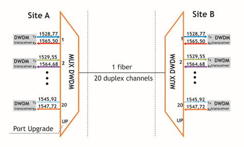
DWDM allows many more wavelengths to be combined onto one fiber. DWDM comes in two different versions: an active solution and a passive solution. An active solution requires wavelength management and is well-suited for applications involving more than 32 links over the same fiber. In most cases, passive DWDM is regarded as a more realistic alternative to active DWDM.
DWDM-mux-demux-function
Benefits of DWDM:
  • Ideal for use in long-haul and areas of greater customer density
  • Up to 32 channels can be done passively
  • Up to 160 channels with an active solution
  • Active solutions involve EDFA optical amplifiers to achieve longer distances
DWDM-with-EDFA
Drawbacks of DWDM:
  • DWDM solutions are quite expensive
  • Active DWDM solutions require a lot of set-up and maintenance expense
  • Very little scalability for deployments under 32 channels, much unnecessary cost is incurred per channel
To sum it up, CWDM can be typically used for applications that do not require the signal to travel great distances and in locations where not many channels are required. While for applications that demand for a high number of channels or for long-haul applications, DWDM is the ideal solution.
Considerations for Deploying WDM
Making sure that the CWDM and DWDM will perform properly is critical, so one should account for the following aspects for when deploying.
1.Before buying a mux or demux for use in an unconditioned cabinet or splice case, verify that the operating temperature will fit the application. And ensure that the CWDM or DWDM will be able to operate within the temperatures in which they will be placed.
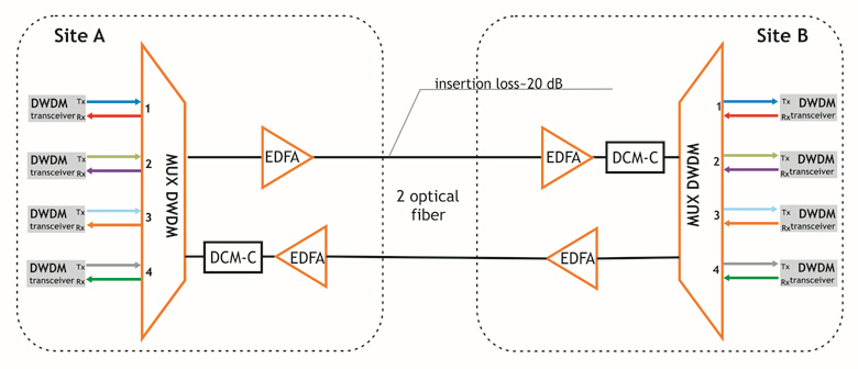
2.Take the insertion loss of WDM network into account. Using the maximum insertion loss value in the link budget is a good idea. Calculate the loss for both the mux and demux components.
Conclusion
WDM technology provides an ideal solution for fiber exhaust problem that many communication providers are experiencing. It eliminates the need for investing on new fiber construction projects while greatly increases fiber capacity of the existing infrastructure. Hope what presented in the article could help you to choose the right WDM solution.

Friday, February 3, 2017

Fiber Optic Cable: Storage & Handling Tips

The prevalence of fiber optic cable has become a trend which is embraced globally, since optical fiber offers unsurpassed advantages. Fiber optic cables are sensitive to excessive pulling, bending, twisting, crushing and other impact forces, for any such damage may alter the fiber property and may pose threats to its performance. So, optical cable should be stored and handled in an appropriate way. This article offers recommendations for proper storage and handling of fiber optic cable.
Fiber Optic Cable Storage
Fiber optic cable can be basically categorized into indoor fiber optic cable and outdoor fiber optic cable. Indoor cables are used exclusively within buildings whereas outdoor cables are employed in outside plant applications. Here are some factors to consider for indoor and outdoor storage.
Indoor Fiber Optic Cable Storage Recommendations
    • Always keep the reel tag that comes with the cable. There is vital information on the tag which indicates the cable description, attenuation, bandwidth and cable length. All these are valid identification of the fiber optic cable for future traceability.
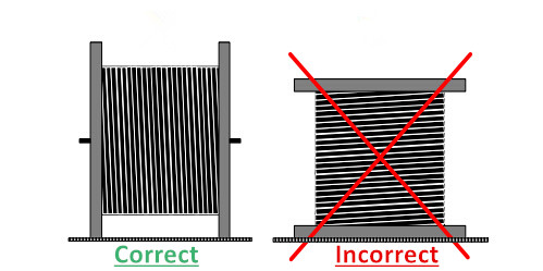
    • Store fiber optic cable reels standing on both flanges, or held through center. Never store a cable reel sitting on one flange surface, which will result in possible future cable damage when unwinding.
indoor optical fiber storage
  • Once rewind the fiber optic cable to another reel, the diameter of the new reel shall be compatible with the minimum bending radius of the cable. And the original cable label details should be copied to the new reel.
  • In no circumstances shall any indoor cable boxes or reels be stored outside or in a harsh environment. Instead, indoor cables should be stored in a dry and UV protected location, such as a room or container.
  • Choose a site for storage with no risk of excessive humidity, falling objects, chemical spills (oil, grease,etc.) open flames or excessive heat. Elements like moisture and other contamination should also be considered when picking storage location.
Outdoor Fiber Optic Cable Storage Recommendations
Requirements listed below are applicable to both outdoor and indoor/outdoor fiber optic cables. Ends of the cables shall be sealed during storage.
    • All fiber optic cable reels including part used should be stored upright. Always store the reel in areas with flat firm surfaces. And use appropriate devices to secure reels to prevent reel movement during storage.
    • Avoid storage areas that are susceptible to flooding, or that could damage the cable, such as sharp, uneven terrain.
    • When the cable reel is too heavy to lift manually, it must be moved upright by lifting the cable with a forklift or reel mover. Never drop a cable reel from any height during transportation or use.
    • When unloading from a vehicle, use either the tail-lift / elevator (if fitted) or a suitable mechanical aid such as a forklift truck. Never let reels drop from the vehicle to the ground.
outdoor fiber optic cable storage
  • Before de-reeling cable, the reel should be visually inspected for possible damage caused during storage.
Considerations for Handling Fiber Optic Cable
Fiber optic cable is prone to damages due to improper handling and such damages can degrade the cable performance. Therefore the following suggestions may be useful to handle fiber optic cable properly.
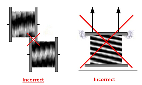
1. Store the cable drums in an upright position, resting it vertically on cable flange edge not in the horizontal position. The flanges of reels shall not be interleaved, and reels must not be lifted by their flanges.
proper handling fiber optic cable
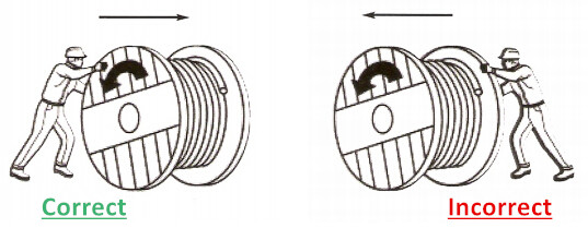
2. The rolling of the drum in the direction of the arrow decreases the chance for the cable to loosen its wind on the drum. However, you should notice that when pulling the fiber optic cable off the drum to install the cable, the arrow will point in the opposite direction to the rotation of the drum. (see the picture below).
proper handling fiber optic cable
3. When moving or handling the drum by a forklift, one should operate it in a proper manner to avoid any damage to fiber optic cable. The fork should not have any direct contact with the cable jacket.
handling fiber optic cable with forklift
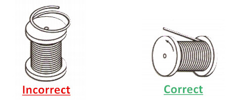
4. While removing fiber optic cable from the drum. It is essential to avoid any reverse bending or twisting that may ultimately deteriorate fiber performance.
proper handling optical fiber
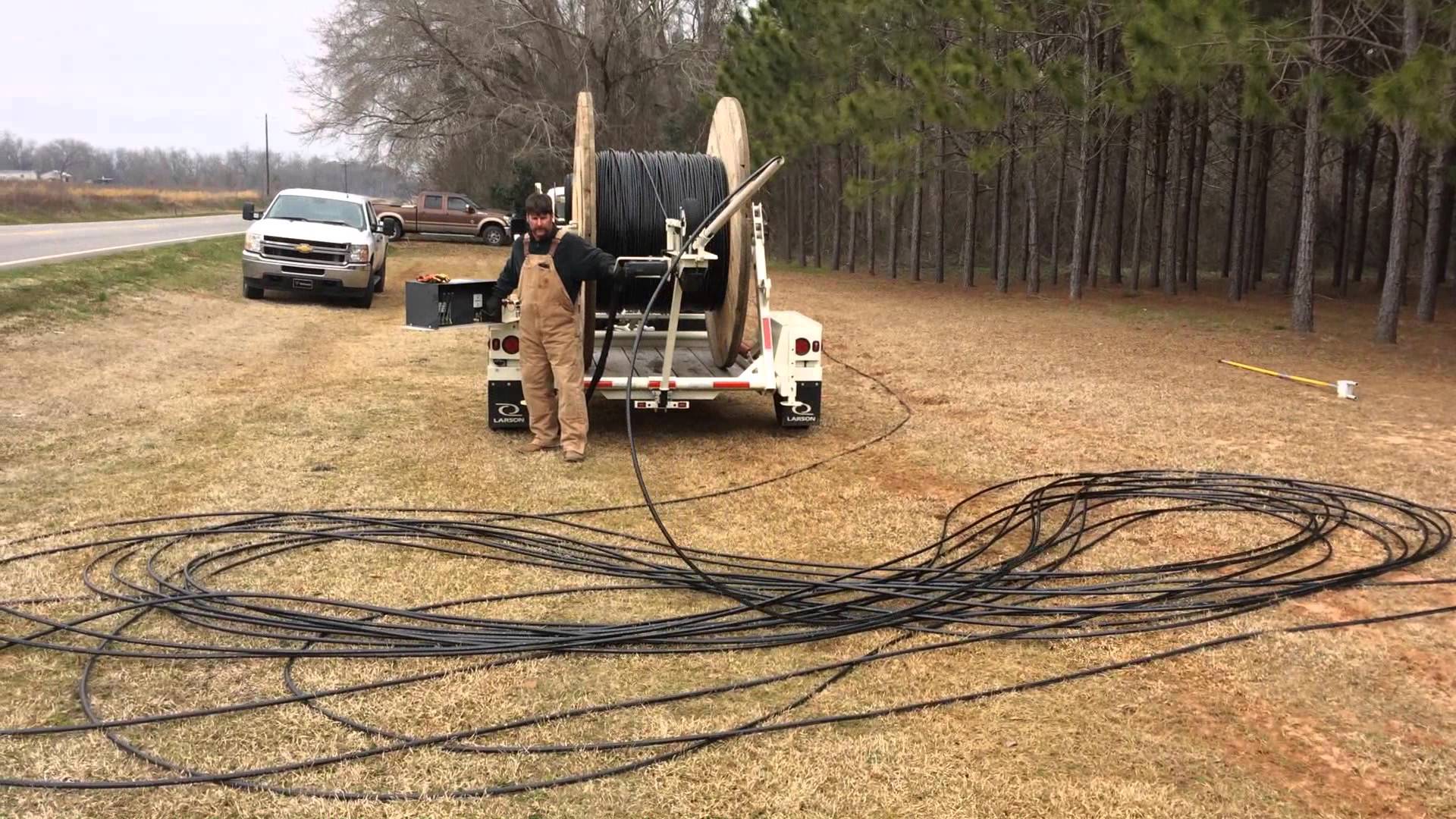
5. Always grounding optical fiber in figure 8 configuration, which allows for pulling of cable in both directions from a central location. It is necessary to protect the figure 8 coil form passers by. The figure 8 coil should be at least 10M by 5M. So what if the longer cable is required to be unreeled? The overwhelming weight of the coil may damage the cable at the bottom. In this case, try to spread the cable out in several figure 8 coils.
fiber optic figure 8 configuration
Conclusion
Proper storage and handling of fiber optic cable help to decreas chances for accidental damages, yet increases longevity of fiber optic cable. This article simply offers a recommended guideline for optical fiber storage and handling, while it is always wise to consult a professional for your unique application.