Thursday, September 22, 2016

40G QSFP+ AOC or 40GBASE-SR4 QSFP+ Transceiver?

As an indispensable and critical part of the whole network system, fiber optic transceiver has been improved extensively to satisfy the increasing demand for higher speed and better performance. Among various transceiver modules on the market, 40GBASE-SR4 QSFP+ transceiver is a commonly applied interconnection solution in data centers for short-distance transmission. Small in size, it can support conversion between optical signals and electrical signals of high data rate. Meanwhile, 40G QSFP+ AOC (active optical cable) also captures a vital position in network interconnections in data centers. This article will make a comparison between these two through five perspectives: transmission distance, reliability, installation and maintenance, digital diagnostic monitoring and cost.

Introduction to 40G QSFP+ AOC

A 40G AOC usually contains a fiber optic cable connected with QSFP+ connectors on both ends. There are also fanout versions of 40G QSFP+ AOC with one end connected with a QSFP+ connector and the other end with several SFP+/XFP connectors. Compared with copper DAC, the interconnection relay on 40GBASE QSFP+ to QSFP+ AOC has more advantages in transmission distance, bend radius, cable size, cable weight and cable management. Compared with 40GBASE-SR4 QSFP+ transceiver, 40G AOC need no optical connectors but perform similarly as the former. Which seems to be a much faster and easier methods for 40G interconnection.
40GBASE-QSFP-AOC

However, everything has its pros and cons. 40G QSFP+ AOC and 40G QSFP+ SR4 transceiver, which one is more suitable for your network system? Let’s figure it out from the following aspects.

Transmission Distance

Optical signals become weaker as the transmission distance increases. Thus, to guarantee data transmission quality, the transmission distance should be the very first aspects to consider. Generally, the transmission distance of 40G QSFP+ SR4 is longer than that of 40G QSFP+ AOC. In 40G transmission, for distance less than 100 m, 40G QSFP+ AOC and 40G SR4 QSFP+ transceiver have nearly the same performances. However, when the transmission distance is longer than 100 m, the performance of 40G QSFP+ AOC would be limited. In this case, 40GBASE-SR4 QSFP+ transceiver would perform better. However, 40G QSFP+ AOC offered by FS.COM is capable of supporting 40G transmission distance up to 300 meters.

Reliability

When dealing with cables and connectors in data centers, it is inevitable to plug them out from switches or servers for regular use and maintenance. With repeat plugging, the reliability and stability of a component become extremely important. Connectors of 40G QSFP+ AOC is factory pre-terminated, while 40G QSFP+ SR4 transceivers is connected by additional MPO connectors and fiber optic cable. Thus, compared with 40G QSFP+ SR4 transceiver, 40G QSFP+ AOC is less affected by the repeating plug during daily use. And with no insertion loss and return loss, it can therefore ensure reliability. In this case, 40G QSFP+ AOC is proven to have better reliability than that of transceiver.

Installation and Maintenance

Both 40G QSFP+ AOC and 40G QSFP+ SR4 transceiver are highly integrated components that provide increased port density and high data rate connection with great convenience during installation and maintenance. However, 40G QSFP+ AOC is superior in this aspect due to it is factory pre-terminated. Just plug the connectors on the devices, the AOC can start working. It eliminates the process of linking two modules, which is a must for interconnection using 40G QSFP+ SR4 transceivers. If an error occurs in the system, you can solve it simply by replacing the AOC. But with 40G QSFP+ SR4 transceivers, you have to test both the MPO connectors and cables. Thus, AOC is easier and faster in installation and maintenance.
40GBASE QSFP+ SR4 transceiver

Digital Diagnostic Monitoring

Digital diagnostic monitoring (DDM) is a function that most modern transceivers have. With this function, the working performance of optics can be visually tested and controlled. With this function, the coupler state and sensitivity of 40G QSFP+ SR4 transceiver can be adjusted to the best. Currently, however, 40G QSFP+ AOC provided by the market doesn’t have such a strong function.
QSFP-SR-40G-testing

Cost

For 40G interconnection, you have to take the cost into consideration, both the material cost and the maintenance cost. Currently the price of 40G QSFP+ AOC is generally lower than 40G QSFP+ SR4 transceiver. To accomplish the connection, additional cost for patch cables should be considered for interconnection using 40G QSFP+ SR4 transceivers. For maintenance, as it was mentioned above, 40G QSFP+ AOC maintenance is faster and easier that do not require much skills, which is believed to be labor saving. So while with limited budget, 40G QSFP+ AOC can be a better alternative.

Conclusion

From what we discussed above, it can be concluded that 40G QSFP+ AOC, with less cost, is more reliable and stable than 40G QSFP+ SR4 transceiver for 40G interconnection. However, it cannot perform as good as 40G QSFP+ SR4 transceiver beyond 100m data transmission. Moreover, with the help of DDM, 40G transceiver can find its best working state that AOC fails to achieve. You’d better choose one based on your specific need and system circumstances. For more information and details, please visit www.fs.com.
Wednesday, September 21, 2016

Ease Fiber Termination With Pigtails

We know the way that cables are attached to the system is quite essential to the performance of the telecommunication network, be it a wiring closet, a building entrance or at points between the transmitter and the receiver. As the cable is connected properly, it enables optical signals to pass with little return loss and low attenuation. Joining optical fibers with a fiber pigtail is proven and considered to be an effective way to ease fiber termination—which is we are going to talk about in this article.

Fiber Pigtail Overview

Also known as bare fiber, fiber pigtail is a kind of optical cable terminated with an optical connector on one end and unterminated fiber on the other. Therefore the end with a connector can be linked to the equipment while the other side is melted together with another optical fiber. In fact, fiber pigtail can be considered as fiber optic patch cable since they are similar in structure, and a fiber patch cable can be divided into two pigtails. Fiber pigtail has various different interfaces and couplers. Common fiber pigtails are usually with 0.9mm fiber cable diameter, and installed inside ODF unit.

Common Classifications of Fiber Pigtail

Fiber pigtails are available with various kinds based on fiber type, connector type and endface type. Some common classifications of fiber pigtail are listed below.

Classified by Fiber Type

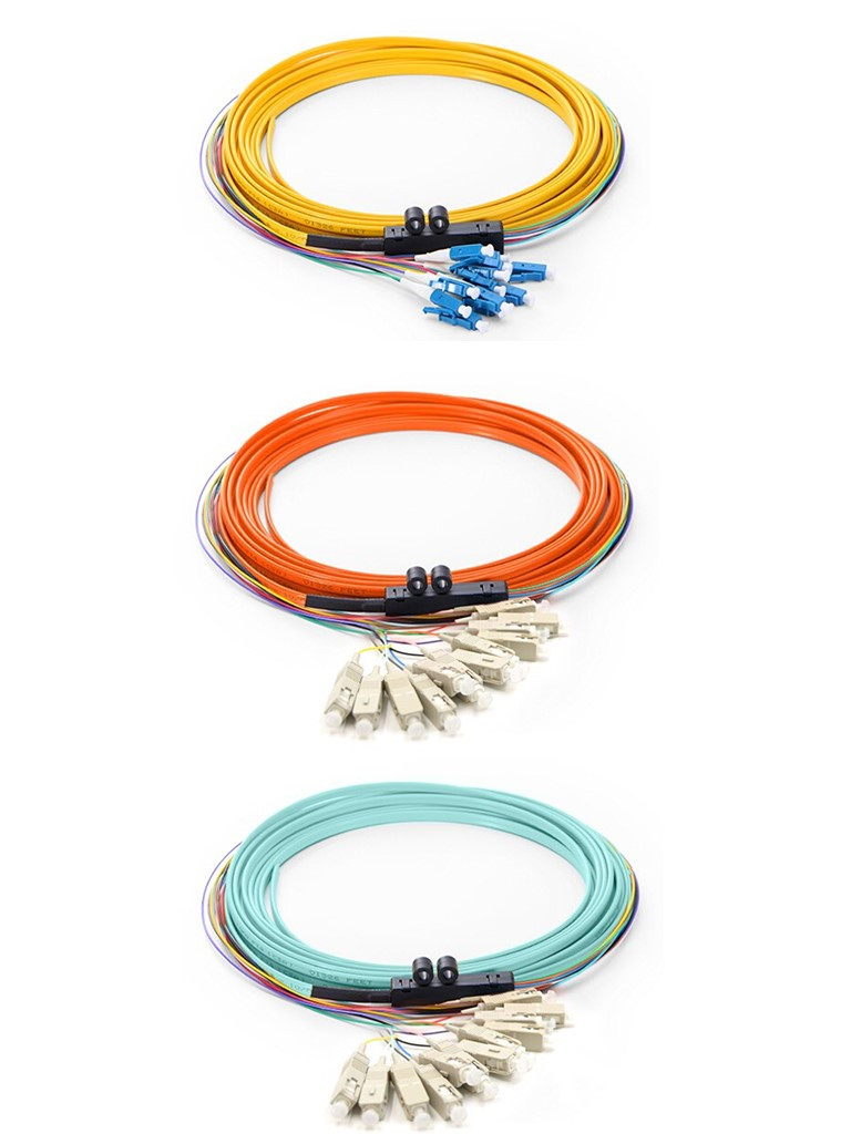
According to fiber type, fiber optic pigtails can be divided into single-mode (colored yellow) and multimode (colored orange) fiber. Multimode fiber optic pigtails use 62.5/125 mm or 50/125 mm bulk multimode fiber cable and terminated with multimode fiber optic connector at one end. Besides, 10G multimode fiber cable (OM3 or OM4) is also available in fiber pigtails. The jacket color of 10G OM3 and OM4 fiber pigtail is usually aqua.
fiber optic pigtail

Classified by Connector Type

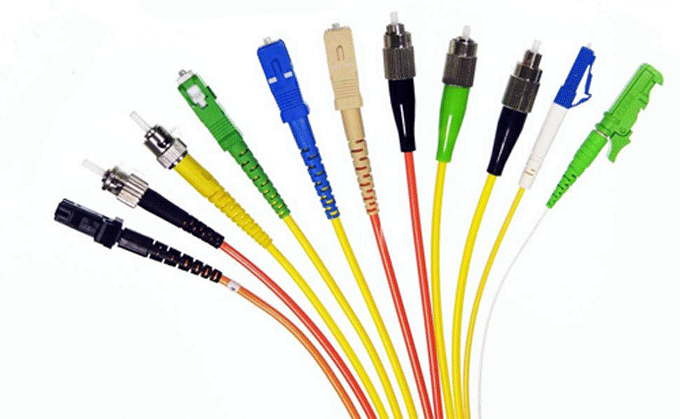
According to different types of fiber connectors that terminated on the end of a fiber pigtail, there are LC fiber pigtail, SC fiber pigtail, ST fiber pigtail, FC fiber pigtail, MT-RJ fiber pigtail, E2000 fiber pigtail and so on. With different structures and appearance, each of them has their own advantages in different applications and systems.
Fiber pigtail connectors

Classified by Endface Type

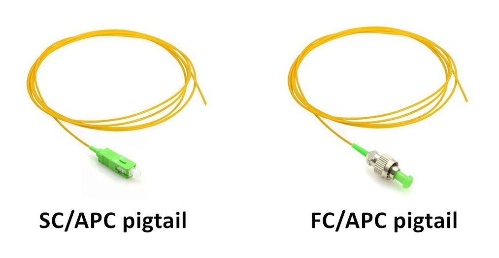
While based on the endface type, fiber optic pigtails can be divided into UPC and APC versions. Most commonly used types are SC/APC pigtail, FC/APC pigtail and MU/UPC pigtail.
SC FC fiber pigtail

Tips for Easier Fiber Termination With Pigtail

As we have explained at the beginning of the article, fiber pigtail plays a crucial role in ensuring the reliability and performance of the system. Meanwhile, it is a rather critical component to ease fiber termination as well. Let’s see how fiber pigtails achieve this.

Selecting Quality Pigtails

Pigtails are attached to cables by fusion or mechanical splicing, both of which provide a fast termination method and hence speed the termination process. While pigtails bridge a critical junction in the fiber-optic network, installers need to choose one made with reliable components. Basically, pigtails are cable assemblies, which means the parts contained in pigtail—a connector, a ferrule, standard fiber and jacket types, are components that every experienced fiber technician is familiar with.
Among these components, however, the quality of the connector stands out as the most crucial one. And elements like insertion loss, the type of polish used and how well the connector is terminated to the cable are extremely vital. Since you have to use fiber and connector types that meets a particular application’s needs. Selecting the proper product depends on job specifications. Ferrule material, whether zirconia ceramic, plastic or stainless steel, must also be specified when ordering a pigtail. Notice that always ordering pigtails a few feet more than you think you`ll need. The extra slack allows for splicing errors to be corrected, or you may have to start with another pigtail.

Saving More Labour Cost and Time

While the majority of single-mode applications use pigtails, they are also used in many multimode applications. One of the benefits of the pigtail is lower labor costs: Installers working with single-mode fiber typically have access to a fusion splicer, and with a fusion splicer you just splice the pigtail right onto the cable in a minute or less.
The quality of fiber pigtail is typically high because the connectorized end is attached in a controlled environment--the factory. And the factory can make single-mode pigtails more accurately than a field termination can be done. Testing a pigtail in the field is not easy, because in the field you are dealing with unknowns, but in the factory, you are dealing with credible measurements. Which on the other hand saves much time spent on field termination.

Conclusion

Fiber pigtail serves as a feasible and reliable solution for easier fiber termination, which effectively contribute to save plenty of operating time and labour cost. The performance of fiber pigtail matters a lot, so the quality of connector, ferrule material as well as cable length of pigtails should be considered to ensure easier fiber termination.

Tuesday, September 20, 2016

Introduction to Types of Fiber Optic Cables

Fiber optic cable has been extensively used in the telecommunication industry due to its immunity to electromagnetic interference, ease of installation and high bandwidth over long distances. The types of fiber optic cables, therefore, can be various. Since different types are for different applications and environments, knowing the feature and distinction of each one would help you to choose the best one for your specific infrastructure. In this article, we will introduce five types of fiber optic cable: indoor fiber cable, outdoor fiber cable, aerial/self-supporting fiber cable, direct-buried fiber cable and submarine fiber cable.

1. Indoor Fiber Cable

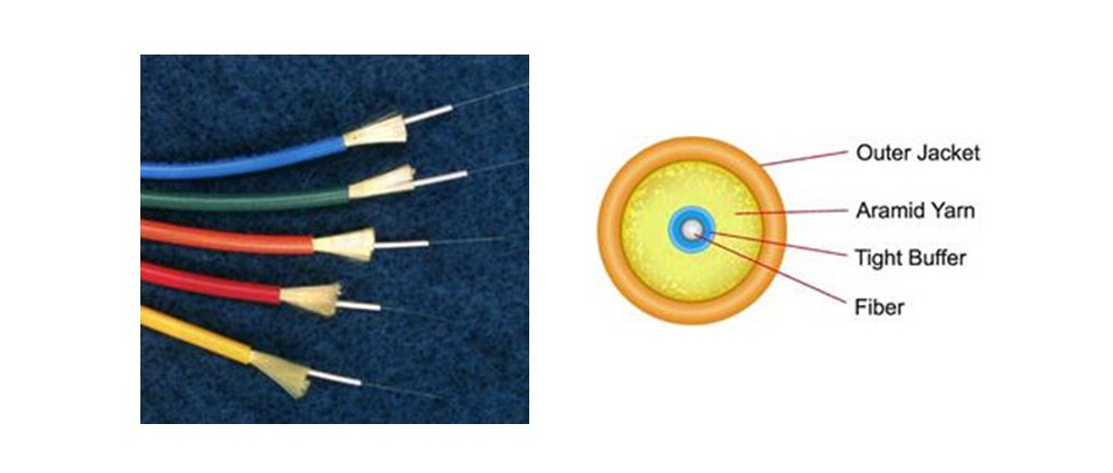
Simplex Fiber Cables
Simplex cables are one fiber, tight-buffered (coated with a 900 micron buffer over the primary buffer coating) with kevlar (aramid fiber) strength members and jacketed for indoor use. Simplex cable varieties include 1.6mm & 3mm jacket sizes. These types are used mostly for patch cord and backplane applications.
simplex fiber cable

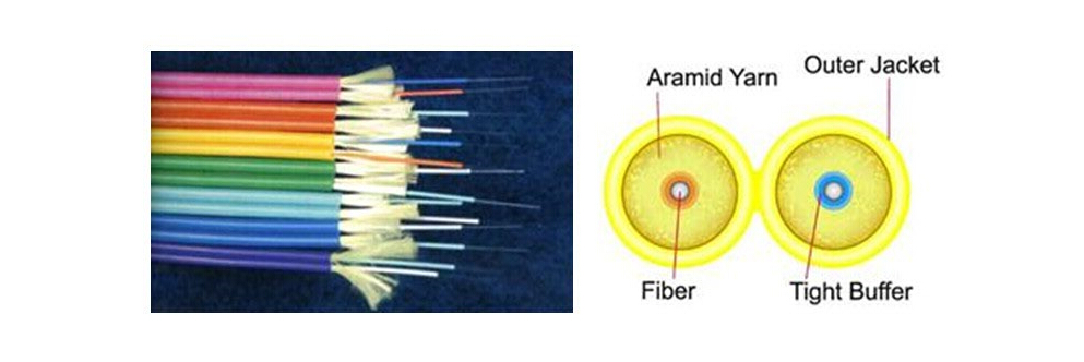
Duplex Fiber Cables
Duplex-zip fiber cable contains two optical fibers in a single cable structure, simply by joining two of them with a thin web. Light is not coupled between the two fibers, typically one fiber is used to transmit signals in one direction and the other receives. Besides being used for patch cord and backplane applications, it can also be employed at desktop connections.
duplex fiber cable

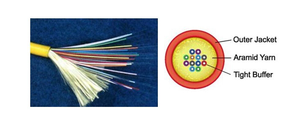
Distribution Fiber Cables
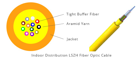
Distribution fiber cable is the most popular indoor cable, as it is small in size and light in weight. This compact building cable consists of individual 900um buffered fiber, connectors may be installed directly on 900um buffered fiber at breakout box location. These cables are used for short, dry conduit runs, riser and plenum applications. The fibers are double buffered and can be directly terminated, but because their fibers are not individually reinforced, these cables need to be broken out with a "breakout box" or terminated inside a patch panel or junction box to protect individual fibers.
distribution fiber cable

Breakout Fiber Cables
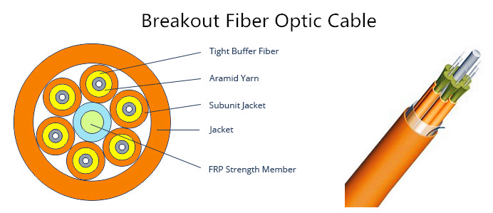
Breakout fiber cables are also called fan-out cables. They are made of several simplex cables bundled together inside a common jacket. Breakout cable is a favorite where rugged cables are desirable, or direct termination without junction boxes, patch panels or other hardware is needed. It is suitable for conduit runs, riser and plenum applications. Because each fiber is individually reinforced, this design allows for quick termination to connectors and does not require patch panels or boxes. Breakout cable can be more economical where fiber count isn't too large and distances too long.
breakout fiber cable

Ribbon Fiber Cables
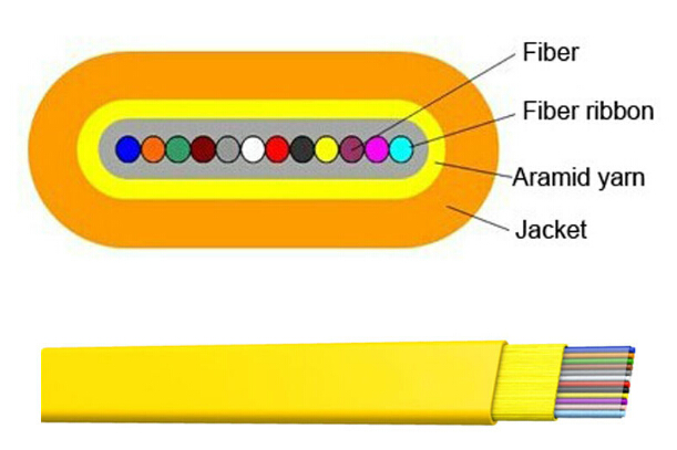
Consists of up to 12 fibers contained side by side within a single jacket. Ribbon fiber cable is preferred where high fiber counts and small diameter cables are needed. This cable has the most fibers in the smallest cable but with the lowest cost. Since all the fibers are laid out in rows in ribbons, typically of 12 fibers, the ribbons are laid on top of each other. Another advantage of ribbon cable is mass fusion splicers can join a ribbon (12 fibers) at once, making installation fast and easy. It is usually adopted in network applications and data centers.
ribbon fiber cable

LSZH Fiber Cables
LSZH refers to low smoke zero halogen cables, they are offered as an alternative to halogen-free applications. Less toxic and slower to ignite, they are a good choice for many internal installations. This cable may be run through risers directly to a convenient network or splicing closet for interconnection.
LSZH fiber cable

2.Outdoor Fiber Cable

Indoor/outdoor Tight Buffered Fiber Cables
Indoor/outdoor rated tight buffered cables have riser and plenum rated versions. These cables are flexible, easy to handle and simple to install. Since they do not use gel, the connectors can be terminated directly onto the 900um fiber without difficult-to-use kits. This provides an easy and overall less expensive installation.
tight buffered fiber cable

Outdoor Loose Tube Fiber Cables
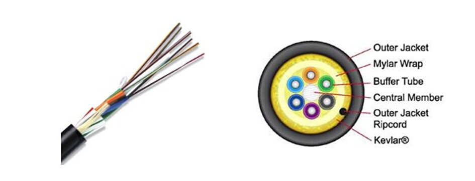
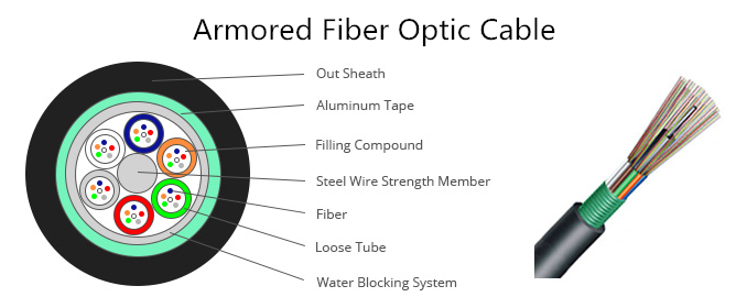
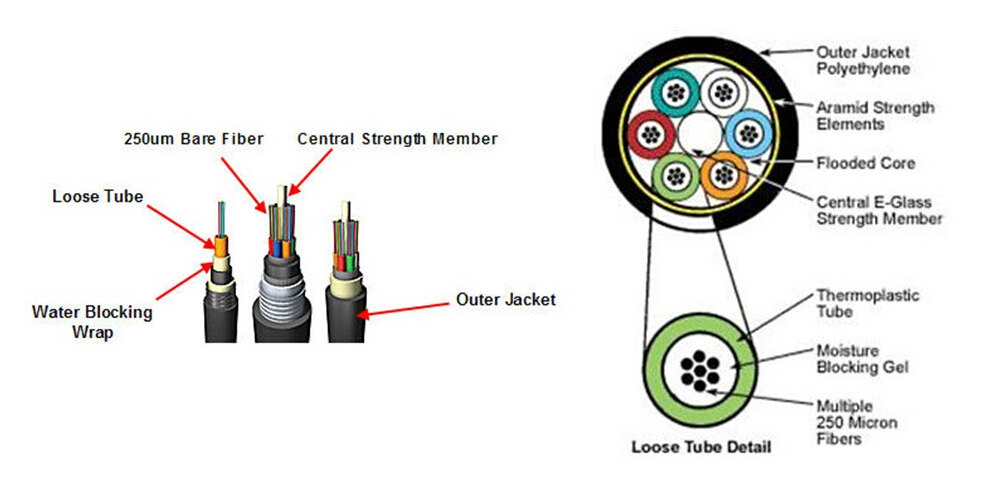
Loose tube cables are the most widely used cables for outside plant trunks because it offers the best protection for the fibers under high pulling tensions and can be easily protected from moisture with water-blocking gel or tapes.These cables are composed of several fibers together inside a small plastic tube, which are in turn wound around a central strength member, surrounded by aramid strength members and jacketed, providing a small, high fiber count cable.
loose tube fiber cable
Loose tube cables with single-mode fibers are generally terminated by spicing pigtails onto the fibers and protecting them in a splice closure. Multimode loose tube cables can be terminated directly by installing a breakout kit, also called a furcation or fan-out kit, which sleeves each fiber for protection.

3.Aerial/Self-supporting Fiber Cable

Known as figure 8 fiber cables as well, this type is designed to be strung from poles outdoors and most can also be installed in underground ducts. It can be lashed to a messenger or another cable (common in CATV) or have metal or aramid strength members to make them self supporting. Aerial fiber cable is easy to install, thus saves a lot of time and cost. Notice that it must be grounded properly.
aerial fiber cable

4.Direct-buried Fiber Cable

Armored fiber cable is used in direct buried outside plant applications where a rugged cable is needed and/or rodent resistance. Similar to outdoor cables but with an outer armor layer for mechanical protection. It withstands crush loads thus can be employed at direct burial applications, or in data centers where cables are installed underfloor, or installed in dusts and aerially. Armored cable is conductive, so it must be grounded properly.
armored fiber cable

5.Submarine Fiber Cable

Submarine fiber cables are used in fresh or salt water. To protect them from damage by fishing trawlers and boat anchors they have elaborately designed structures and armors. Long distance submarine cables are especially complex designed.
submarine fiber cable

Conclusion
As we know, different types of fiber optic cables are of distinct designs and constructions, thus for different applications and environments. What we introduced above are several commonly used fiber optic cables, hope it would offer you some help to find the most suitable one.

Sunday, September 11, 2016

Basics of Mode Conditioning Patch Cable

The 802.3z standard (IEEE) for Gigabit Ethernet over optical fiber was released to satisfy the demand for higher bandwidth. While 1000BASE-LX transceiver modules can only operate over single-mode fibers. Then what if the transceiver must be employed over both single-mode and multimode fibers? The problem of differential mode delay (DMD) occurs when single-mode fiber is launched into a multimode fiber—it will generate multiple signals that confuse the receiver and lead to inevitable errors. If you ever encounter such a problem, a mode conditioning cable is much needed to help. This article is about some rudiments of mode conditioning cable.

What Is Mode Conditioning Patch Cable?

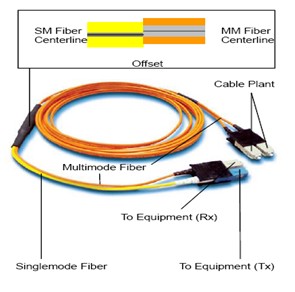
Mode conditioning patch cable functions the same way as a standard patch cable, however, its mode-conditioning unit consists of a cable assembly with an offset single-mode fiber to multimode fiber connection point and duplex connectors on each end. It is basically a duplex multimode cable that has a small length of single-mode fiber at the start of the transmission length. With two multimode fibers on one end and one multimode and one single-mode fiber on the other end. The mode-conditioning patch cord is suitable for long-wavelength multimode applications like Gigabit Ethernet.
mode conditioning patch cable

How Does Mode Conditioning Patch Cable Work?

The basic working principle of mode conditioning patch cable is that, the launch of the light coming out of the equipment begins on a single-mode fiber, and the single-mode fiber is precision fusion spliced to the multimode fiber to a precise core alignment (see picture below). The light is launched on to the multimode fiber at a precise angle, giving the cable its mode conditioning properties.
mode conditioning patch cable working principle

By using an offset between the single-mode fiber and the multimode fiber, mode conditioning patch cords eliminate DMD effectively. And the resulting multiple signals make it possible to use 1000BASE-LX transceivers over multimode fiber systems. This is considered to be a cost-effective and energy-saving solution since there is no need to upgrade the whole fiber plant.

Tips for Using Mode Conditioning Patch Cable

Mode conditioning patch cables are available from various vendors on the market, so it is important to know where and when they should be used.

1.Mode conditioning cable is normally used in pairs. That means that you will need this cable at each end to connect the equipment to the cable plant. So then, these cables are usually ordered in even numbers. The usual reason why someone may order one cable is so they may keep it as a spare.

2.If your Gigabit Lx switch is equipped with SC or LC connectors, be sure to connect the yellow leg (single-mode) of the cable to the transmit side, and the orange leg (multimode) to the receive side of the equipment. It is imperative that this configuration be maintained on both ends. The swap of transmit and receive can only be done at the cable plant side. (see the picture below)
MCP connecting

3.Mode conditioning patch cords can be only used for single-mode to multimode conversion. If you want to convert multimode to single-mode, then a media converter will be required.

Mode Conditioning Patch Cable Installation

Looking at the mode conditioning cable assembly in the following picture, we can see that the fusion splice is protected by a black over-wrap. On the left side there is an orange and a yellow cable, and this is the side of the cable that connects to the gigabit equipment, with the yellow single-mode leg to be connected to the transmit side.
mode-conditioning-patch-cable

Here we provide some steps to follow when installing mode conditioning patch cable:
  • Step1: Connect the yellow leg (single-mode connector) of the cable into the transmit bore of the transceiver.
  • Step2: Connect the rest orange legs (multimode connectors) of the cable into the receive bore of the transceiver.
  • Step3: At the other end of the patch cord, put all the orange legs (multimode connectors) into the patch panel.
  • Step4: Repeat the above three steps for the second transceiver located at the other end of the network link.

Conclusion

Mode conditioning patch cable offers an optimum solution for improving data signal quality and increasing transmission distance. It is available with various options of different connectors, jackets and lengths. Hope this article could provide you some useful information and constructive suggestions.

Friday, September 9, 2016

Analysis of Two Basic Fiber Structures: 250um and 900um

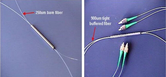
As we know that there generally exist two basic structures of fiber—loose-tube 250um fiber and tight-buffered 900um fiber, have you ever wondered what the difference is between them? Actually loose-tube 250um fiber and tight-buffered 900um fiber both start with the same 250um bare fibers. Therefore, they feature the same size fiber core (50 um for multimode and 9 um for single-mode), 125um cladding and soft 250um coating. The difference between the two, however, lies in the cable construction.

The Structure of 250um Fiber and 900um Fiber

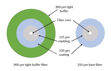
Most of the fibers come down to two basic configurations—250um coated fiber (also called bare fibers) and tight-buffered 900um fiber. Actually tight-buffered fibers cover a coated fiber (the coating is soft plastic) with a thick layer of harder plastic, making it easier to handle and providing physical protection. So, let’s firstly look at the structure of each fiber.
250um and 900um fiber

The Structure of a 250um Coated Fiber (Bare Fiber)
  • Core (9um for standard single mode fibers, 50um or 62.5um for multimode fibers)
  • Cladding (125um)
  • Coating (soft plastic, 250um is the most popular, sometimes 400um is also used)

The Structure of 900um Tight-buffered Fiber
  • Core (9um for standard single mode fibers, 50um or 62.5um for multimode fibers)
  • Cladding (125um)
  • Coating (soft plastic, 250um)
  • Tight buffer (hard plastic, 900um)
250um-Bare-Fiber-vs.-900um-Tight-Buffer-Fiber

The Differences Between Loose-tube 250um Fiber and Tight-buffered 900um Fiber

Based on 900um tight buffered fiber and 250um coated fiber there are two basic types of fiber optic cable constructions—loose-tube 200um cable and tight-buffered 900um cable. So, next we will explain the difference between them.

Differences in the Layer

Distinct from loose-tube 200um fiber, tight-buffered 900um fiber adds an additional 900um layer of hard plastic over the 250um fibers for protection. Within the cable, several of these color-coded 900um tight buffered fibers are situated around a central strength member, and then covered with Kevlar or aramid yarn for protection, a rip cord and then the jacket.
tight-buffered fiber optic cable

Fiber counts of tight-buffered 900um fiber cable typically range from 2 to 144 fibers, with larger fiber counts featuring fiber subunits of 6 or 12 fibers within the cable. For example, a 144-fiber cable usually has twelve 12-fiber subunits while a 36-fiber cable could have six 6-fiber subunits or three 12-fiber subunits.
 

Differences in the Tubes

Loose-tube 250um fiber places up to 12 bare 250um fibers inside a flexible plastic tube, which are also color coded and situated around a central strength member with Kevlar or aramid yarn for protection. The fiber counts of loose-tube 250um fiber cable range from 6 to 144, and besides the 6-fiber cable, the fibers are also grouped into sets of 12 for maximum density. Loose-tube 250um fiber cables are less than half the size of 900um fiber cables.
loose-tube fiber optic cable

Buffered loose-tube cables feature an outer waterblocking tape around the tubes, beneath the outer jacket. The tubes are gel-filled to prevent water migration, or they are available with a dry waterblocking technology—sometimes referred to as gel-free cable. These materials are proved to be essential to prevent water from migrating into the tubes, as well as protect the fiber from freezing, expanding and breaking by water. Meanwhile, the dry waterblocking technology also dramatically reduces installation time by eliminating the need to clean off the gel prior to termination.

Applications of 250um Fiber and 900um Fiber

Generally, tight-buffered 900um fiber cables are usually employed for indoor applications, like intra-building riser, plenum applications and in data centers, whereas loose-tube 250um fiber cables are typically used in outside plant (OSP) applications, such as inter-building duct, aerial and direct buried installations.

Indoor/outdoor cables have the advantage of eliminating the need for service entrance splicing to in-building cable. And OSP loose-tube 250um cabling must be terminated within 50 feet of entering a facility. So, breakout kits are used to build the 250um cable up for protection and termination to 900um connector boots. With breakout kits, therefore, will add material costs and a significant amount of labor. One option is to terminate the 250um fiber directly to 250um connector boots. This can speed network deployment in the data center and fiber-to-the-home applications.

Conclusion

To sum it up, the difference of loose-tube 250um fiber and tight-buffered 900um fiber mainly lies in the cable construction, that tight-buffered 900um fiber with an additional layer and loose-tube 250um fiber with a gel-filled or waterblocking tube. Knowing the configurations and features of fiber cables would help to make an optimum alternation in different occasions and applications.

Tuesday, September 6, 2016

How to Select the Right Rack Mount Fiber Enclosure?

Fiber enclosure is a vital component that often used to organize cables and protect fibers in fiber optic cabling and terminations. And it is extensively used in specific fields like data centers, server rooms, FTTX, CATV and so forth. Since data center configurations and requirements can be various, different types of rack mount fiber enclosure is designed to meet those special needs. The right fiber enclosure can effectively boost network performance, enhance working efficiency and reduce expenditure. So here we will introduce several types and designs of rack mount fiber enclosure and offer some suggestions on how to select the right one.

Types and Designs of Rack Mount Fiber Enclosure

As one of the most commonly used fiber enclosure in data center, rack mount fiber enclosure provides a convenient and rugged termination point for fiber jumper cables. This rack mount enclosures offer a flexible connectivity system using a variety of adapter plates and MPO cassettes.

Rack Mount Enclosure Configurations

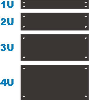
The rack mount fiber enclosure is generally made for standard 19 inch rack mounting. Depending on the number of connections required, they are available in one or more rack units (RU) height configurations, such as 1RU, 2RU or 4RU, etc. The following picture shows different size of enclosure configuration, and according to it, you could choose the most proper one depending on the space and requirements of your project.
rack unit

Cover Removable Type, Slide-out Type or Swing-out Type

Generally, there are three types of rack mount enclosure: fiber enclosure with a removable lid, slide-out fiber enclosure and swing-out type enclosure. The slide-out type and swing-out type is generally more expensive than the cover removable type, but with these two designs, you can benefit a lot during cable installation and maintenance, since you do not need to remove the whole enclosure from the rack to gain internal access. It is proved to be time and energy saving.
types of rack mount fiber enclosure

Fixed Front Panels or Removable Front Panels

As for the design of the fiber enclosure front panel, there exist fixed front panel and removable front panel. The fixed front panel can be loaded with appropriate fiber optic adapters, while the removable front panel can accommodate several fiber optic adapter panels or cassettes. Nowadays, the removable front panel is becoming more popular because a plug & play fiber adapter panel assures flexibility and ease of network deployment.
front panel of fiber enclosure

Applications of Rack Mount Fiber Enclosure

Basically, rack mount fiber enclosure can be used in the following three circumstances.

For Fiber Splicing Joints

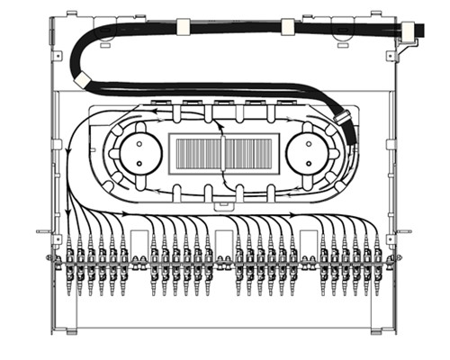
For fiber splicing joints in fiber enclosure, splice tray and FAPs are needed. When installing four fiber adapter panels on the front panel and one or more splicing trays inside the enclosure drawer, this fiber enclosure can provide cable management and protection for splicing joints and connections.
fiber splicing joints fiber enclosure

For Patch Cord Connections

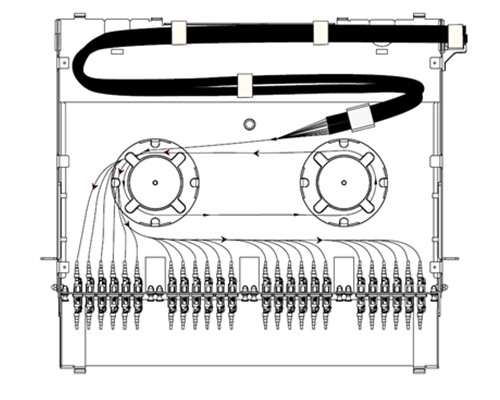
This kind of fiber enclosure usage is very common. Simply by installing two slack spools and four fiber adapter panels on the fiber enclosure, it could make fiber patch cables management much easier. The following picture shows a breakout fiber patch cable installed in the fiber enclosure and being well organized by the spools.
patch cord connection fiber enclosure

For MTP to LC Interface Transferring

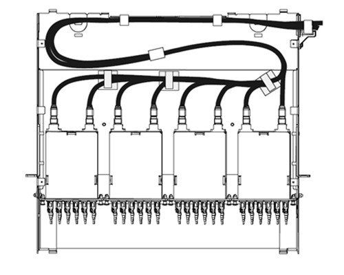
The popularity of 40G/100G network makes the transferring between 40G/100G MTP interfaces and 10G LC interfaces an important issue. MTP cassettes are widely used to reduce installation time and ensure the connection quality. A 1U rack mount fiber enclosure can hold up to 4 HD MTP cassettes. The picture below shows the fiber enclosure with four HD MTP cassettes which are connected by several input MTP trunk cables.
MTP to LC interface transferring fiber enclosure

Guide to Select Rack Mount Fiber Enclosure

In this part, we will solve the problems that troubled some data center operators—how to choose the most suitable rack mount fiber enclosure. Here we offer a reference guide for you to follow.

Physical requirement

First, list all the requirement of the enclosure and the complete measurements: height, depth, width, and weight, which will ultimately determine what type of rack mount fiber enclosure you need. Note that always select a bigger fiber enclosure for all your existing equipment and for future growth.

Critical accessories

A fiber enclosure should provide plenty of access points through the rear and top of the cabinet, as well as through the bottom for raised floor installations. Not only are the fiber optic cables mounted in the fiber enclosure, but devices like hubs, routers, patch panels, and monitors are needed to be mounted in the enclosure-network. Remember that any accessories that are not rack-mountable will require additional trays, shelves and mounting accessories.

Budget

Choosing an affordable rack mount fiber enclosure that within your installation budget serves as a basic requirement. We sometimes are stuck in a dilemma that whether to choose an equipment optimum for now or the expensive one for future. However, a premium rack mount fiber enclosure is a durable item that will provide services for years to come.

Conclusion

Rack mount fiber enclosure has become increasingly popular in data centers to ensure better cable management and maintenance. Besides, it can also be employed for fiber splicing joints, patch cord connections and MTP to LC interface transferring. Since several types and designs are available, just making the choice based on your specific need, then take the physical demand, accessories and budget into consideration. For more information and details about fiber enclosure, please visit www.fs.com.
Friday, September 2, 2016

Common Ways to Test Optical Fiber Cable

As the popularity of bandwidth-intensive applications has increased continuously, demand for fiber optic installations and infrastructures has accelerated parallelly. Optical fiber cable thus has possessed a rather essential position in telecom industry. However, the testing of optical fiber cable is often considered to be one of the most confusing and misunderstood phases of installing a fiber optic system, meanwhile it is also one of the final and most important procedures in installing optical network. Then how to deliver valid optical fiber cable testing? Here, we introduce you three most common methods.

Why Optical Fiber Cable Testing Matters

Let’s start by talking about the importance of optical fiber cable testing. Proper testing of optical fiber cable increases the system’s longevity, minimizes system downtime, reduces maintenance needs, and supports system upgrades and reconfigurations. And all these contribute significantly to your network performance, reliability and manageability in the long run.

Optical Fiber Cable Testing Methods

Fiber optic cable is tested to ensure continuity and attenuation. Basically, there are three test methods commonly performed for optical fiber: visible light source, power meter and light source (one jumper method), and optical time domain reflectometer (OTDR).

Visible Light Source Testing

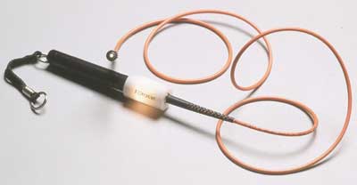
Visible light source tests optical fiber continuity. Optical fiber communication systems operate in the infrared region of the electromagnetic spectrum which is invisible to the human eye. However, (red) visible light sources are available for testing and troubleshooting optical fiber systems. They are also referred to as visual fault locators and visual fault finders.
visual fault locator

When testing optical fiber cable with a visible light source, you could follow the suggested procedures:

Step 1. Connect the optical fiber flashlight to one end of a fiber strand (with most units, the fiber must be terminated).

Step 2. Look at the opposite end. (Notice: Be careful not to look directly at active optical fiber strands. Laser light sources can cause serious eye damage.)

Step 3. If the light is not visible at the opposite end, a break or other problem is likely present somewhere along the length of the fiber. In many instances, the fault location will glow red from the light of the visible light source.

Step 4. Document the test result information.

Power Meter and Light Source Testing

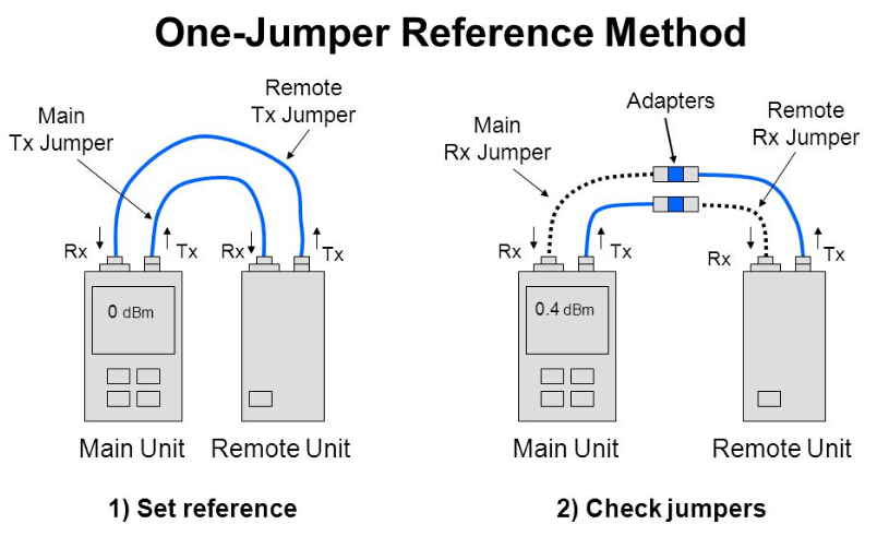
Power meter and light source testing, also known as the one jumper method, is the most accurate way to measure end-to-end signal loss of the fiber, referred to as attenuation. Listed below are TIA/EIA- 568 insertion loss limits for the various components. Specific installations or protocols may impose stricter limits.

Loss budget (TIA/EIA specification limits)
Element Insertion Loss
Splice < 0.3 dB at all wavelengths
Connector Pair < 0.75 dB at all wavelengths

Test results should be compared to the link attenuation allowance calculated as follows:

Link Attenuation Allowance (dB) = Cable Attenuation Allowance (dB) + Connector Insertion Loss Allowance (dB) + Splice Insertion Loss Allowance (dB)
one jumper testing method

When testing optical fiber cable with power meter and light source, perform the following steps.

Step 1. Disconnect active equipment.

Step 2. Acquire suitable light source for the single mode (generally 1310 nm or 1550 nm), multimode (850 nm or 1300 nm), and power meter.

Step 3. Verify proper wavelength to set source and meter. (Note: Calibration of the equipment is required before each test. Follow the equipment manufacturer’s procedures.)

Step 4. Acquire accurate test jumpers and couplers, which should be part of the light source and power meter kit.

Step 5. Connect the jumper (containing the same fiber size as the system fiber) to the optical source and the optical power meter. Turn unit on. Record the reference power reading (Pref), displayed in dBm.

Step 6. By applying an adapter, insert a second jumper (Test jumper 2) between the jumper used in Step 5 and the optical power meter. Verify the attenuation added by the second jumper is not greater than 0.75 dB: Pref-Pcheck ≤ 0.75 dB.

Step 7. Attach the jumpers to the optical source and optical power meter. Disconnect the two jumpers at the adapter. Connect the optical source/Test jumper 1 to one end of the system fiber to be tested. Connect the optical power meter/Test jumper 2 to the other end of the system fiber. Document the test power (Ptest). Subtract the test power (Ptest) from the reference power (Pref), recorded in Step 5, to conclude the end-to-end attenuation: Attenuation (dB) = Pref-Ptest.

Step 8. Document the test results.

Optical Time Domain Reflectometer (OTDR) Testing

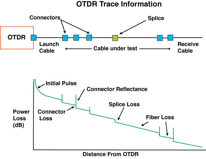
Optical time domain reflectometer (OTDR) measures the fiber cable length, attenuation, and “events” along the length of the fiber. Here, the events can be splices, breaks, or stress points that cause excessive attenuation. The OTDR does this by sending light pulses down the cable and measuring the timing and power of light reflected back to the OTDR by the events and the fiber itself. It uses this information to display a “trace”, which is a graph of power versus distance.

An OTDR only requires access to one end of a fiber for testing. Because an OTDR is an indirect measurement method, it is not as accurate as a light source and power meter for measuring attenuation. However, due to its ability to display a graph of the fiber, it is particularly useful in troubleshooting. Like a power meter and light source, an OTDR tests at specific wavelengths (generally 1310 nm and/or 1550 nm for single mode and 850 nm or 1300 nm for multimode).
OTDR testing

Conclusion

Appropriate understanding of the testing methods and referencing procedures plays a critical role in testing accuracy for both legacy and future systems. Among these three methods mentioned in the article, which one to choose actually depends on your specific needs and real circumstances. Hope what we discussed above could fix your problems and assist you to deliver better optical fiber testing.

PC, UPC or APC – Selecting the Right Fiber Connector

When describing fiber connectors, we often use terms like “LC UPC simplex single-mode fiber connector” or “ SC APC simplex single-mode fiber connector”. Then have you ever wondered what “UPC” and “APC” stand for? Or is there any difference between them? This is what we are going to talk about in this article.

Introduction to Different Kinds of Fiber Connector

Firstly, let’s take a look at how connectors evolve from the original flat fiber connector into the physical contact (PC) connector and then onto ultra physical contact (UPC) connector and angled physical contact (APC) connector.

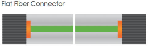
Flat Fiber Connector

When two flat fiber connectors are mated together, a small air gap is left between the two ferrules. This is partly because the relatively large endface of the connector allows for numerous slight but significant imperfections to gather on the surface. However, it is not much use for single-mode fiber cables with a core size of just 8-9 um, hence there naturally comes to the necessary evolution to physical contact (PC) connectors.
Flat Fiber Connector

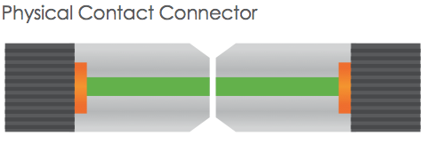
Physical Contact Connector

The PC connector is similar to the flat fiber connector but it is polished with a slight spherical (cone) design to reduce the overall size of the endface. Which helps to decrease the air gap issue faced by regular flat fiber connectors, resulting in lower optical return loss (ORL), with less light being sent back towards the power source.
Physical Contact Connector

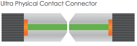
Ultra Physical Contact Connector

Ultra physical contact connector (UPC) is built on the convex endface attributes of the PC, but with an extended polishing method, which creates an even finer fiber surface finish. This results in lower back reflection (ORL) than a standard PC connector, allowing more reliable signals in digital TV, telephony and data systems, where UPC today dominates the market. UPC connectors do have a low insertion loss, but the back reflection will depend on the quality of the fiber surface and, following repeat matings/unmatings, it will begin to deteriorate.
Ultra Physical Contact Connector

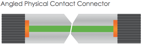
Angled Physical Contact Connector

The tendency is that the industry needs a connector with low back reflection, that could sustain repeated matings/unmatings without ORL degradation. And this brings us the angled physical contact (APC) connector.

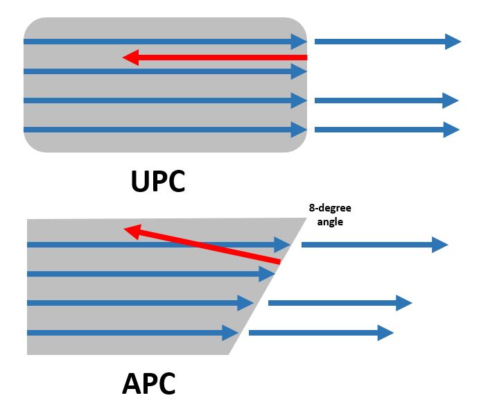
Although PC and UPC connectors have a wide range of applications, some instances require return losses in the region of one-in-a-million (60dB). Only APC connectors can consistently achieve such performance. This is because adding a small 8-degree angle to the endface allows for even tighter connections and smaller endface radii. Combined with that, any light that is redirected back towards the source is actually reflected out into the fiber cladding, again by virtue of the 8-degree angled end-face. What to mention is that other three connectors are all inter-mateable, whereas the APC isn’t.
Angled Physical Contact Connector

Differences Between UPC and APC

Currently, with UPC and APC connectors dominating the market, these two types are the most commonly seen connectors employed in the fiber optic industry. In this part, we will mainly explain the difference between them. Besides the more obvious difference that UPC connectors are blue while APC connectors are green, the main difference actually lies in the fiber endface.
UPC and APC

APC connectors feature a fiber endface that is polished at an 8-degree angle, while UPC connectors are polished with no angle. UPC connectors are not exactly flat however, they have a slight curvature for better core alignment. With UPC connectors, any reflected light is reflected straight back towards the light source. However, the angled endface of the APC connector causes reflected light to reflect at an angle into the cladding versus straight back toward the source. This causes some differences in return loss, which is a measurement of reflected light that is expressed as a negative dB value (the higher the value, the better). Industry standards recommend that UPC connector return loss should be -50dB or greater, while APC connector return loss should be -60dB or greater.

Selecting the Right Fiber Connector

With APC connectors being used by most cable companies, other FTTX providers in outside plant applications, and passive optical applications (both GPONs and passive optical LANs). Future higher-speed passive optical networks and other WDM applications that will use higher wavelengths via singlemode fiber will also likely require the reduced return loss of APC connectors. What should be noted is that APC and UPC connectors cannot be mated, in case to cause poor performance or to destroy both connectors. However, when choosing the right connector for your specified application, factors like cost and simplicity should also be considered seriously, not just optical performance. So, it actually depends on the real circumstances and various factors.

Conclusion

It is generally accepted that all of these connector options capture a place in the current market, and we cannot say anyone is better than the others since whether to choose UPC or APC in fact depend on your particular need. Whereas for those applications which high precision optical fiber signaling matters, APC should be the optimum alternative, but for less sensitive digital systems, UPC and APC can both perform equally well.