Thursday, September 20, 2018

Switch vs Router vs Modem: What Is the Difference?

Ethernet switch, router and modem look strikingly similar if only judging by their appearance. However, they each play different roles and are deployed for various purposes in a network. So what is the key difference of switch vs router vs modem? How switch vs router vs modem each functions in a network. We would address these issues in this article by explaining switch vs router vs modem from scratch.
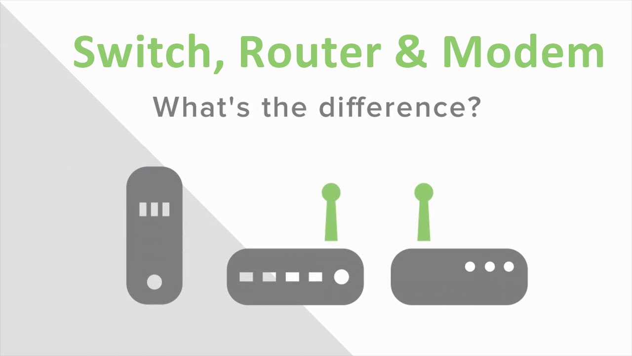
switch vs router vs modem

Switch vs Router vs Modem: All Are Major Network Devices

We’ll start from exploring what exactly network switch, router and modem are and the roles of switch vs router vs modem in a network.
modem router switch diagram
What Is a Modem?
A modem is often provided by your ISP (Internet Service Provider) which enables a network access to the internet. In some cases ISPs provide "hybrid" modem/router combination, this device might be power efficient to some extent, it actually limits your network potentials. So suggestion is to request a standalone modem whenever possible to increase the available resources on the network.
What Is a Router?
When connecting more than one device to a modem, a router is generally required. A router acts as the "traffic director" of a network. It takes information provided by the modem and routes it to the devices attached to the modem, then the router creates Network Address Translated ( NAT) internal private IP address to the connected devices so they can be accessed. Devices like computers, game consoles and etc can be connected to a router wirelessly or through network cables. Some advanced features of a router includes built-in firewall to help protect the network from unwanted traffic.
What Is a Switch in Networking?
A switch (such as a 10GbE switch or Gigabit PoE switch) is used to provide additional ports, expanding the capability of the router. A network switch learns the association between the MAC addresses of connected devices and its switched ports. A switch only sends data to where it needs to go, thus reducing the amount of data on the network, thereby increasing the overall performance of the connected devices while improving security. Often connected to a router, a switch will not provide routing capability and should not be connected directly to the modem unless a DHCP server is present elsewhere on the network.

Switch vs Router vs Modem: Similarities and Differences

As standard components in Ethernet networks, switch vs router vs modem bears many similarities, but there are also some key characteristics to set them apart.
Similarities:
  • Switch vs router vs modem are all small plastic/metal box-shaped electronic device
  • They all allow computers to connect to it for the purpose of enabling communication among them via Internet Protocol
  • They all have some physical ports on the front or back of them, which provide the connection points for computers, a connection for electric power, and LED lights to display working status.
Differences:
Router vs Modem
Routers work at network layer 3 of the OSI model, and it deals with IP addresses. A router is specifically used to join networks together and routes traffic between them. When used at home, your router connect the internal local network to your ISP’s network. And it can be connected to your modem (provided by ISP) on one end and to a switch on the other end (local network). Usually, the Internet port on a router will connect to your modem and the rest of the ports are for switches. A modem has a single coaxial port for the cable connection from your ISP and a single Ethernet port to link the Internet port on your router. Modem is used to connect your ISP using phone line (for DSL), cable connection or fiber (ONT).
Router vs Switch
Like we’ve mentioned, a router works at layer 3 of the OSI model, thereby it allows you to connect multiple computers to each other and also allows them to share a single Internet connection. A switch, however, works at layer 2 of the OSI model (there are also some layer 3 switches that have routing capacities), which connects one point to another in a network temporarily by turning it on and off as necessary. Note that a switch only allows you to connect multiple computers into a local network. The following chart illustrates other differences concerning router vs switch.
Router
Switch
Function
Directs data in a network. Passes data between home computers, and between computers and the modem.
Allow connections to multiple devices, manage ports, manage VLAN security settings
Layer
Network Layer (Layer 3 devices)
Data Link Layer. Network switches operate at Layer 2 of the OSI model.
Data Transmission Form
Packet
Frame (L2 Switch) Frame & Packet (L3 switch)
Used
LAN, MAN, WAN
LAN
Transmission Mode
Full duplex
Half/Full duplex
Broadcast Domain
In Router, every port has its own Broadcast domain.
Switch has one broadcast domain [unless VLAN implemented]
Speed
1-100 Mbps (Wireless); 100 Mbps - 1 Gbps (Wired)
10/100 Mbps, 1 Gbps
Address used for data transmission
IP Address
MAC address
Used for
Connecting two or more networks
Connecting two or more nodes in the same network (L2) or different network (L3)
Faster
In a different network environment (MAN/ WAN), a router is faster than an L3 switch.
In a LAN environment, an L3 switch is faster than a router (built-in switching hardware)
Features
Firewall VPN Dynamic hadling of Bandwidth
Priority rt range On/Off setting of port VLAN Port mirroring

Switch vs Router vs Modem: What’s the Connection Sequence?

The simple rule for connecting switch, router and modem is like this: modem-router-switch (access point)-multiple clients. Put the switch behind a router so all devices connected to either the switch or the router can access the internet simultaneously, while placing the switch right after the modem is just as equal to not putting it - it will waste some of your hardware and cables since all your switch ports aside from the two going between the router and modem will be useless to you.
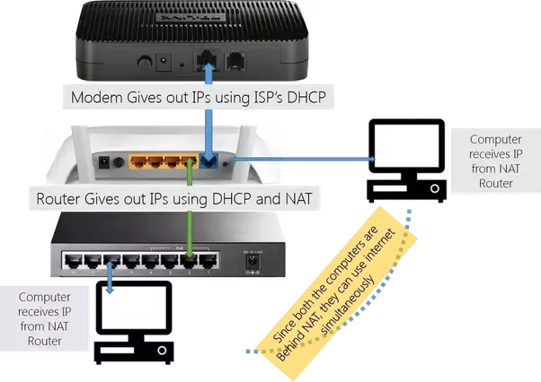
how to connect switch, router and modem

Conclusion

Here we’ve walked you through the basic concept of switch vs router vs modem, as well as the similarities and differences concerning router vs modem and router vs switch. Hope that has clear some of your confusions. For any further solution related to fiber switch or network router, reach us via sales@fs.com.
Source: http://www.cables-solutions.com/switch-vs-router-vs-modem-difference.html
Sunday, September 16, 2018

Server Rack Cable Management: What Is the Best Practice?

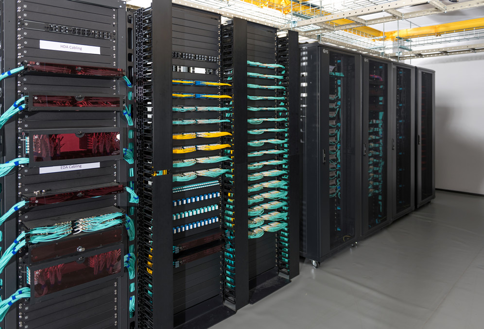
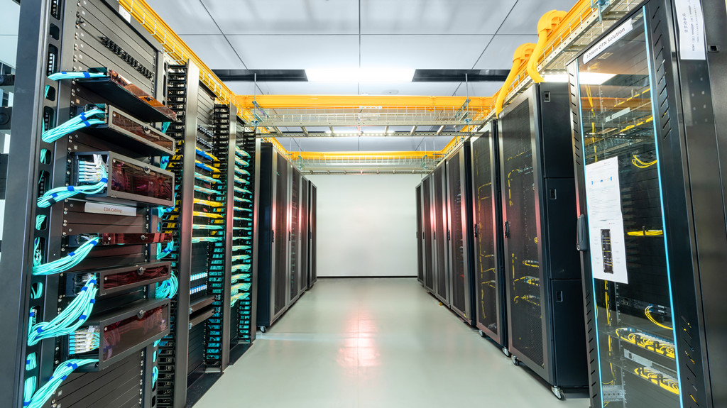
Data centers today consist of rows of server racks and network cabinets to support an abundance of data cables, power cords and network devices. Deliver proficient cable management within a confined and tightly-spaced server rack is quite difficult. However, cable management is no longer a nightmare if you follow the right guide and work with some test-and-tried tools. Here we’d like to offer useful advice for server rack cable management, and recommend some efficient and reliable management tools.
server rack cable management

Server Rack Cable Management Benefits

Server rack cable management, if not being handled properly, could bring you a succession of problems – it would result in cable damage and failure, which directly lead to data transmission errors, performance issues and system downtime. On the contrary, successful cable management in server rack can benefit you in every aspects, including:
Improved system performance: server rack cable management demands to separate power and data cables within the racks, which greatly decrease the chance for crosstalk and interference.
Enhanced availability: Effective server rack cable management allows easier access to cables and IT devices, yet to reduce human error.
Improved maintenance and serviceability: Effective rack cable management also ensures easier and safer access to individual components.
Increased cooling efficiency: let hot exhaust air out from the back, server rack cable management keeps cables organized and out of critical airflow paths.
Improved scalability: cable management in server rack simplifies moves, adds, and changes, making it easier to integrate additional racks and components for future growth.

Server Rack Cable Management Guide

Since we’ve made clear the benefits of server rack cable management, here is a step-to-step guide for you to further explain how to do it correctly:
  • Plan appropriately. It greatly contributes to smooth server rack management process. Consulting a professional cabling contractor can always be beneficial.
  • Determine the routes for power and data cables. Determine if they enter from the top or bottom of the server rack. Then plan the routes to separate power and data cables, and copper data cables and fiber.
  • Identify cables. Use colored cables as well as cable labers to ensure easier cable identification.
  • Route and retain cables. Cables must be protected at points where they might encounter sharp edges or heated areas. Cable ties and cable managers can be used to this end.
  • Secure cables. Cables and connectors should be secured to prevent excessive movement and to provide strain relief of critical points.
  • Avoid thermal issues. Ensure the airflow path is rather important, since restrained airflow can cause temperatures rise that would shorten devices’ expected lifespan.
  • Document and maintain organization. Documenting the complete infrastructure including diagrams, cable types, patching information, and cable counts is important.

Efficient Tools for Server Rack Cable Management

Here are top five management tools that can facilitate cable management in server racks:
1. Horizontal Cable Manager
Horizontal cable managers are excellent for any kind of cable – fiber, coax, patch cables, copper wiring and more to ensure that your cables are well-organized and protected. Horizontal cable managers come with rack-mountable 1U or 2U design, and some of them are built with finger duct and D-rings for easier finger access in server rack.
2. Vertical Cable Manager
Vertical cable manager work very well to organize and hold cables to ensure proper air flow, avoiding overheating in complex server rack environment. They’re also great for installations where you need to save space or need to make more room in the future to expand your network.
3. Cable Hangers and Trays
If you need to organize cabling within server racks, cable hangers can come in handy. Cable trays are excellent for running wires from one place to another and can be mounted on the floor or overhead in the ceiling.
4. Copper Patch Panels
For data and telecommunications networks a copper patch panel is essential. A patch panel is a board with a number of different ports to connect network wiring. Ethernet patch panels are available in a variety of different configurations depending on your cable types and needs: there are Cat5e patch panel, Cat6 patch panel and Cat6a patch panel, each with different port counts such as 24-port patch panel, 48-port patch panel, etc. Copper patch panel is also great for consolidating cables so that your server rack looks neat and organized.
5. Fiber Optic Patch Panels
Similar to data patch panels, fiber patch panels are designed specifically for fiber optic cables. Also known as termination units they can accommodate connectors, patch cables and more. Network technicians can easily connect cable fibers through cross connection, test the cable patch panel, and connect it to other network equipment. Grouping by the connector type, there are single mode and multimode LC/SC/MTP fiber patch panels with various port counts. You can also choose blank patch panel to mix and match your fiber and copper cabling.

Conclusion

Effective server rack management helps to improve physical appearance, cable traceability, airflow, cooling efficiency and troubleshooting time while eliminates the chance for human error. Hope our guide on server rack cable management would help solve your problem. FS.COM provide tailored cable management solutions for our customers, as well as management tools like cable manager, patch panelcable organizer and cable tie. If you need any help, please contact us at sales@fs.com.

Source: http://www.cables-solutions.com/server-rack-cable-management-practice.html

Friday, September 7, 2018

GUI vs CLI: Which for Managing Network Switch?

Network switch is the major building block of many business networks, as they connect multiple PCs, printers, access points, servers, and other hardware to make your business up and running. Switches enables you to send and receive information and access shared resources in a smooth, efficient and highly secure way. It happens at some points we need to make settings or adjustments on switches to perform certain function, like configuring VLAN or check status of switch ports. So how to get the configuration access to a network switch? Does GUI or CLI work better for you? What’s the difference between GUI vs CLI? We’ll address these issues and guide you to manage switch via GUI and CLI.
gui vs cli for configuring network switch

What Is GUI (Graphical User Interface)?

GUI is short for Graphical User Interface – it uses graphics like windows, scrollbars, buttons, etc. to allow users to communicate with the data switch or GUI operating system. It facilitate users, especially novice users in an intuitive and easy-to-learn way. GUI access need recognition and good exploratory analysis and graphics, which is more suitable for users who requires no access to advanced tasks.
what is command line cli

What Is CLI (Command Line Interface)?

CLI stands for Command Line Interface, which allows users to write commands in a terminal or console window to communicate with an operating system. CLI acts as the medium between operators and the network switch: Users have to type command to perform a task. CLI is more accurate than GUI, but it has a very steep learning curve. CLI is appropriate for users who uses it in a regular basis, or for the costly computing where input precision is the priority.
what is gui graphical user interface

GUI vs CLI: What Is the Difference?

GUI vs CLI, both as the mainstream interface for accessing network switch, differs in the following aspects:
Ease of Use: CLI enable users to type manual command in order to perform the desired task whereas in GUI users provided visuals to communicate with the data switch. So the beginners will pick up a GUI much faster than a CLI.
Control: With a GUI, there’s control over files and the operating system – but advanced tasks may still need CLI. While CLI enables all the control over file system and operating system, making tasks simple.
Speed: In GUI, using the mouse and the keyboard to control is slower than using the command line. With CLI, the operator simply use the keyboard and may need to execute only few commands to complete the task.
Hacking: In terms of hacking, all the vulnerability exploits are done from command line. All the remote access and file manipulation are done from the command line.
Scripting: CLI excels in this field since it allows you to create a script that contains few lines of command and it will do the work for you.
Here we use the chart to summarize GUI vs CLI differences.
BASIS FOR COMPARISON
CLI
GUI
Basic
Command line interface enables a user to communicate with the system through commands.
Graphical User interface permits a user to interact with the system by using graphics which includes images, icons, etc.
Device used
Keyboard
Mouse and keyboard
Ease of performing tasks
Hard to perform an operation and require expertise.
Easy to perform tasks and does not require expertise.
Precision
High
Low
Flexibility
Intransigent
More flexible
Memory consumption
Low
High
Appearance
Can't be changed
Custom changes can be employed
Speed
Fast
Slow
Integration and extensibility
Scope of potential improvements
Bounded

GUI vs CLI: How to Use Them to Manage Network Switch?

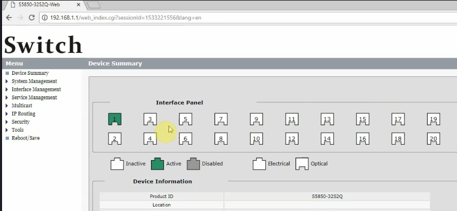
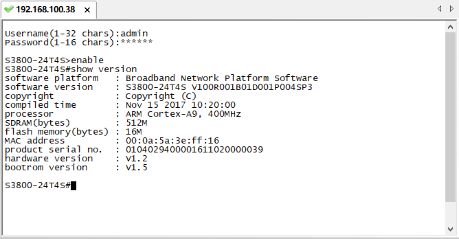
CLI and GUI are different kinds of user interfaces with their own merits and drawbacks. It is important to understand where each one excels so you can pick the right tool. Using the defining features of two different tools provides the best of both worlds. The following video, using FS S5850-32S2Q 10GbE switch as an example, offers a complete guide on how to use command line and GUI to access a network switch, through which you may figure out which one fits better for you.

Conclusion

In all, the GUI provides a higher degree of multitasking and more efficiency, whereas CLI offers more control, precision and repeatability. The decision on choosing GUI vs CLI to configure the network switch should better based on user requirements. FS.COM offers a comprehensive product line of network switches, including Gigabit Ethernet switch, Gigabit PoE switch, etc. If you are seeking network switch configuration or management solutions, feel free to contact us at sales@fs.com.

Source: http://www.cables-solutions.com/gui-vs-cli-manage-network-switch.html

Sunday, August 26, 2018

Server Rack Choice: How to Make It Right?

Data centers and server rooms house an abundance of server rack cabinets, which work to organize IT equipment into assembly order to make the most use of space and resources. Your daily operation and maintenance rely significantly on the server rack choice since it greatly affect the network reliability, serviceability and manageability. Not all the server racks are created equal, so we will walk you though some critical aspects for choosing the right server rack.
server rack buying guide

What Is a Server Rack and Why We Need It?

Typically made of steel or aluminum, rails and framework, a server rack is capable of holding hundreds or even thousands of pounds of equipment. For now, the vast majority of IT applications use 19-inch server racks and equipment. As the width of which is always the same, the height and depth can be various. Server rack is designed to hold all standard 19-inch rack-mountable equipment, as long as it isn’t too deep for the cabinet or too high to fit in the available rack spaces. Moreover, server rack also holds IT infrastructures and rack accessories that support the operation of the production equipment, including UPS systems, PDUs, cable managers, KVM switches, patch panels and shelves.

Common Server Rack Types

Basically, there are two types of server racks: rack enclosures (or rack cabinets) and open-frame racks. And based on where they are used, rack enclosures and open-frame racks are further divided into floor-standing server rack and wall-mount server rack.

What Should I Look for a Rack?

There exist a dazzling array of rack options, in terms of different heights, sizes and styles. When selecting the rack for your installation, here are some factors to consider:
Server rack size
Be sure to accurately assess the amount of rack space you need while allow for future growth. So always pay attention to the height and depth of a server rack. The height of a rack is expressed in "rack units" (a rack unit is 1.75 inches, or 44.45mm). The actual height of a 42U rack is therefore 42 x 1.75 = 73.5 inches.
AV vs. IT-based installations
The choice should better depend on the equipment being installed. IT racks are designed for traditional IT equipment in which the I/O and cabling is on the front of the rack. This makes easier troubleshooting and network monitoring. AV racks are typically shallower in depth, enabling a cleaner installation by using equipment with rear facing I/O.
Airflow and cooling
These two factors are critical to the performance and longevity of the equipment installed in the rack. Depending on the airflow condition of the place the rack located, you may need to increase the rack’s cooling capability.
Equipment width
With 19-inches being the traditional standard for rack mounted network hardware, some vendors make custom sizes for other types of equipment. Make sure to check what size of rack your equipment requires.
Security options
While there might be a great amount of expensive equipment installed on the rack, you have always to bear security in mind. A rack that meets the security goal is thus essential. Locking cabinet and tinted door glass can help protecting your network from prying eyes and hands.

Conclusion

The right server rack type that meets your demand helps you improve power protection, cooling, cable management, and physical security. Hope the knowledge and suggestions offered in this article will help you choose the perfect server rack/server rack cabinet. Taking the above factors into consideration and thinking thoroughly before making the choice. Should you ever need a server rack or associated cable management accessories such as fiber optic patch panel, Ethernet patch panel and cable organizer, feel free to contact us at sales@fs.com

Monday, August 20, 2018

PPPoE vs DHCP: What is the difference?

PPPoE vs DHCP may sound like two irrelevant items since the application of each are not the same: DHCP is a protocol for obtaining IP addresses while PPPoE is a common method of connecting to an ISP. But the debate over PPPoE vs DHCP differences has been around for a long time and thus causes a lot confusions. So in this article we will have PPPoE vs DHCP explained and walk you through how they differ from each other.

PPPoE vs DHCP: DHCP Wiki

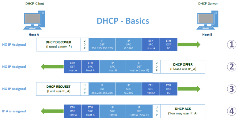
DHCP, or Dynamic Host Configuration Protocol, is a standardized client/server network protocol that dynamically assigns IP addresses and other related configuration information to network devices. It is known that each device from a TCP/IP network should have a unique IP address to access the network. So without DHCP configuration, network admins have to configure IP addresses manually if they want to add new computers or move computers from one subnet to another. Usually, a DHCP architecture is made up of DHCP clients, DHCP servers and DHCP relay agents.
dhcp wiki
DHCP works to offer an automated way to distribute and update IP addresses and other configuration information on a network. A DHCP server provides this information to a DHCP client through the exchange of a series of messages. DHCP enables network users to travel anywhere on the network and automatically receive an IP address when they reconnecting. On the other hand, DHCP provides network admins quicker and more reliable IP address configuration – it mitigates configuration errors caused by manual IP address configuration. DHCP also helps to conserve limited IP address space.

PPPoE vs DHCP: What Is PPPoE?

PPPoE, short for Point-to-Point Protocol over Ethernet, is an Ethernet encapsulation of the Point to Point Protocol that is commonly used with dial-up connections. This allows the modem to be a part of the network that multiple users can utilize instead of being connected directly to the computer. PPPoE combines the Point-to-Point Protocol (PPP), commonly used in dialup connections, with the Ethernet protocol, which supports multiple users in a local area network. The PPP protocol information is encapsulated within an Ethernet frame. To employ PPPoE, you need a username and a password provided by your ISP, which you use to dial-up to your ISP and establish a connection. More recent modems now incorporate the PPPoE dialer into them. You can simply set your username and password once and your modem automatically connects to the internet whenever you turn it on.
what is pppoe

PPPoE vs DHCP: How They Differ?

DHCP is a way for a network to allocate unique IP addresses to the devices (i.e. computers, smartphones Gigabit Ethernet switch and etc.) within a network, so that traffic can be delivered back-n-forth without confusion. PPPoE is a way to encapsulate network traffic, based on credentialed access (i.e. username/password). PPPoE needs to be configured correctly before a user can actually connect to the internet, however, modems that use DHCP does not need to be configured and is basically plug and play. So using DHCP to connect to an ISP eliminates the problems that are associated with PPPOE. Just like with computers on a network, you do not need to configure your computer beforehand. You simply leave everything on automatic and leave the configuration to the ISP servers.
The difference between PPPoE vs DHCP can be summarized as following:
  • DHCP is a protocol for obtaining IP addresses while PPPOE is a common method of connecting to an ISP
  • DHCP is very popular and is widely used while PPPOE is slowly falling out of favor
  • You would need to have a username and password with PPPOE while the configuration of DHCP is automatic

Conclusion

So we’ve explored the definition of each term and major PPPoE vs DHCP differences. It is thus to conclude that there is no “one is better than the other”- PPPoE and DHCP serve two entirely different purpose without overlap. Hope it would help to clear out your confusion. Backed by a professional tech team, FS.COM has improved solutions for network devices like Ethernet routers, fiber switch (i.e. 10 Gigabit switch) and servers. To get any further information, reach us via sales@fs.com.

Source: http://www.cables-solutions.com/pppoe-vs-dhcp-difference.html
Thursday, August 9, 2018

What Is IPv6 And Why Is It Important?

IPv6 has been around for over a decade but is not yet seeing broad adoption. However, with the imminent exhaustion of available IPv4 addresses, the lack of IP addresses has become a more pressing problem. As the successor of IPv4, IPv6 will not only offer far more addresses, but will address assignments and additional network security features. What is IPv6 and how does it matters? What’s the differences between IPv4 vs IPv6? Let’s get some insight into these issues.
what is ipv6 protocol

What Is IPv6 and How Does It Matter?

IPv6 (Internet Protocol Version 6) is a network layer protocol which allows communication and data transfers to take place over the network. IPv6 came into existence in 1998 and was created out of the concern that demand for IPv4 addresses would exceed availability. IPv6 protocol, which is 128-bits, consists of eight numbered strings, each containing four characters, separated by colon. This gives us an unbelievable amount of unique IP addresses. Despite these, IPv6 protocol also simplifies address assignment (for computers) and provides additional security features. It greatly solves network bottleneck caused by the soaring amount of Internet-connected devices.

Advantages and Disadvantages of IPv6 Protocol

IPv6 protocol is all about future-proofing, with which every current household could have trillions of connected devices, each with their own individual IP addresses, and there would still be plenty of IPv6 addresses to spare, without the need for NAT. Here are the pros and cons of IPv6.
Pros of IPv6 Ptotocol
  • Increased Capacity: of address space—resources are efficiently allocated to accommodate additional web addresses.
  • Efficient Routing: allows for easy aggregation of prefixes assigned to IP networks.
  • Efficient Data Flow: enables large data packets to be sent simultaneously helping to conserve bandwidth.
  • Security: is improved due in part to improved authentication methods built into network firewalls.
Cons of IPv6 Ptotocol
  • Conversion: IPv4 is still widely used and the world is slow to convert to IPv6, the process of making the switch to IPv6 from IPv4 is slow and tedious.
  • Communication: IPv4 and IPv6 machines cannot communicate directly to each other, in the very rare circumstance that they would need to.
  • Readability: Understanding IPv6 subnetting can be difficult on its own, let alone trying to remember/memorize your IPv6 address.

IPv4 vs IPv6: What’s the Difference?

IPv4 protocol consists of four number strings – each containing three digits separated by dots. A standard IPv4 address is 32-bit and allows 4.2 billion unique IP addresses. By comparison, IPv6 uses longer IP addresses: with eight groups of four hexadecimal digits, separated by colons. Hence IPv6 significantly expands the pool of IP addresses. Besides, it also frees the internet from relying on NAT because of the dearth of IPv4. Ipv6 enables all devices to be accessible on the public network for easier management. Moreover, IPv6 is much secure than IPv4 at making sure Internet traffic gets to the correct destination without being intercepted.
ipv4 vs ipv6

What You Need to Enable IPv6

IPv6 has not yet put IPv4 into obsolescence, but we should at least get fully prepared for it. It would be better to make sure that any future PC, mobile device and gigabit Ethernet switch/router support IPv6 protocol. To use IPv6, you’ll need three things:
  • An IPv6-Compatible Operating System: Your operating system’s software must be capable of using IPv6. All modern desktop operating systems should be compatible.
  • A Ethernet Switch/Router With IPv6 Support: Check your network switch/router’s specifications to see if it supports IPv6 if you’re curious. Or when the need occurs, try to grasp network switch/router with IPv6 function.
  • An ISP With IPv6 Enabled:Your Internet service provider must also have IPv6 set up on their end.

Conclusion

IPv6 is rolling out steadily, but slowly. As IPv6-only networks can dramatically simplify network operations and keep costs down, there is reason to believe the trend will continue. It’s important to prepare for the future and get IPv6 working, however, there is no need to race to implement this or worrying about it too much. FS.COM offers IPv6 enabled 10GbE switch and other copper/fiber switch with advanced feature sets that can fit your varying demand. For further information, contact us via sales@fs.com.

Sunday, July 29, 2018

OpenFlow Switch: What Is It and How Does it Work?

SDN (Software-Defined Networking) technology is generating huge interest in networking industry due to its ability to add higher agility and scalability for networks. At the core of the SDN technology is the OpenFlow protocol, and SDN with OpenFlow switch promises flexibility and fast configuration of communication networks. So what exactly is OpenFlow and OpenFlow switch? How does OpenFlow switch work to improve network agility and scalability? We try to explain it in detail and clear out the confusions.

What is OpenFlow and OpenFlow Switch?

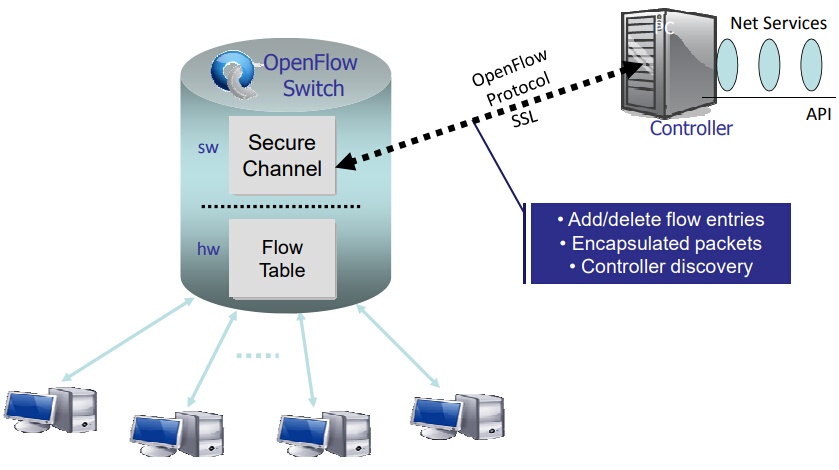
OpenFlow is a programmable network protocol for SDN environment, which is used for communication between OpenFlow switches and controllers. OpenFlow separates the programming of network device from underlying hardware, and offers a standardized way of delivering a centralized, programmable network that can quickly adapt to changing network requirements.
openflow protocol
An OpenFlow switch is an OpenFlow-enabled data switch that communicates over OpenFlow channel to an external controller. It performs packet lookup and forwarding according to one or more flow tables and a group table. The OpenFlow switch communicates with the controller and the controller manages the switch via the OpenFlow switch protocol. OpenFlow switches are either based on the OpenFlow protocol or compatible with it.
what is openflow switch

How Does OpenFlow Switch Work?

An OpenFlow switch can only function with the collaborate work of three essential elements:  flow tables installed on switches, a controller and a proprietary OpenFlow protocol for the controller to talk securely with switches. Flow tables are set up on switches. Controllers talk to the switches via the OpenFlow protocol and impose policies on flows. The controller could set up paths through the network optimized for specific characteristics, such as speed, fewest number of hops or reduced latency.

OpenFlow Switch vs Conventional Switch: What’s the Difference?

In a conventional switch, packet forwarding (the data plane) and high-level routing (the control plane) occur on the same device. While for an OpenFlow switch, the data plane is decoupled from the control plane: with the data plane implemented in the switch itself but the control plane in software and a separate SDN controller makes high-level routing decisions. The switch and controller communicate by means of the OpenFlow protocol. OpenFlow switch hence boosts the following advantages:
  • With OpenFlow switch, the SDN controller could route non critical/bulk traffic on longer routes that are not fully utilized.
  • The SDN controller can easily implement load-balancing at high data rates by just directing different flows to different hosts, only doing the set-up of the initial flow's.
  • Traffic can be isolated without the need for vlan's, the SDN controller of OpenFlow switch can just refuse certain connections.
  • Setup a network TAP/Sniffer easily for any port or even specific traffic by programming the network to send a duplicate stream to a network monitoring device.
  • OpenFlow switch allows for the development of new services and ideas all in software on the SDN controller, as well to accelerate new features and services.

Why OpenSwitch Is the New Trend?

OpenFlow switch is designed to provide consistency in traffic management and engineering, by making control function independent of the hardware it's intended to control. This combination of open source software and commodity hardware holds the potential for unprecedented efficiency and operational agility, which fitted well in the world where network becomes increasingly diverse and demanding. Enabling OpenFlow on physical switches and move to OpenFlow switch is something that most clients have been working toward. FS.COM switch product line consists of 10GbE switch, 40GbE switch and 100GbE switch that supports OpenFlow 1.3, which can be used as OpenFlow switches in open networking environment.
10G SDN Switch with L2/L3 ICOS, 48*10GbE ports + 6*40GbE ports
40G SDN Switch L2/L3 ICOS, 32*40GbE ports
100G L2/L3 Switch Loaded with ICOS, 48*25GbE ports +6*100GbE ports

Conclusion

OpenFlow switch addresses bottlenecks to high performance and scalability in SDN environments. Providing an efficient, vendor-independent approach to managing complex networks with dynamic demands, OpenFlow switch is likely to become commonplace in large carrier networks, cloud infrastructures, and other networks. FS.COM SDN OpenFlow switch has received great reputations from our customers, for more information, just reach us via sales@fs.com.

Sunday, July 22, 2018

SFlow vs NetFlow vs SNMP: What Are the Differences?

Effective network monitor and traffic management are vital for ensuring peak network performance. While SFlow, NetFlow and SNMP offer different means to monitor network traffic, a question arises from time to time: SFlow vs NetFlow vs SNMP, which is better? These article will provide some insights into the issue by addressing differences between SFlow vs NetFlow, SFlow vs SNMP and NetFlow vs SNMP. However, the best solution always depends on your network condition and the resources at hand.
network monitoring-sflow vs netflow vs snmp

SFlow vs NetFlow: SFlow for Multiprotocol, NetFlow for Better Accuracy

SFlow vs NetFlow, the debate between these two flow protocols has been around for many years. SFlow was developed by InMon Corporation. It is designed to be compatible on many different platforms of switches and network routers, which allows SFlow to grow in popularity. SFlow uses a dedicated chip that is built into the hardware, which removes the load from CPU and memory. SFlow is sample based, so accurate representation of 100% of the traffic per interface is nearly impossible.
what is sflow
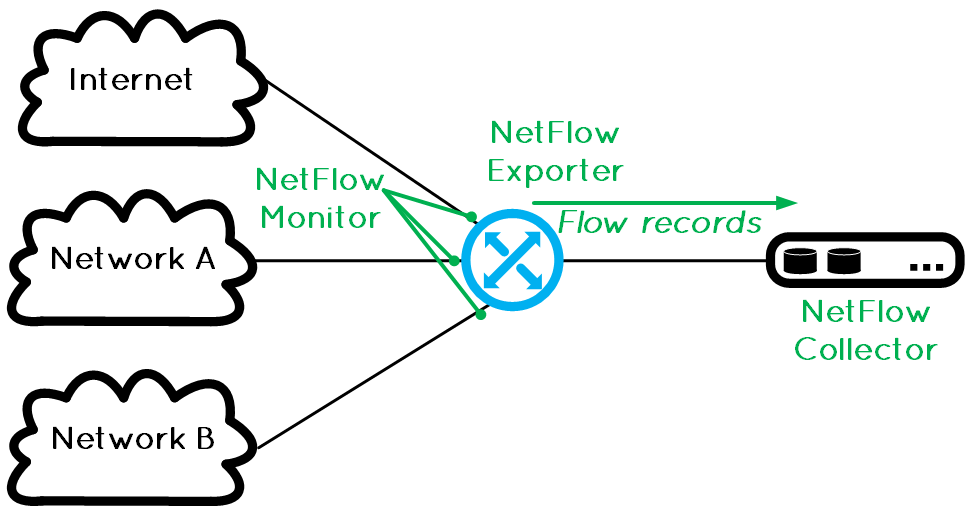
Then what is Netflow? NetFlow started as a proprietary technology developed by Cisco. It is presented in Cisco switches and routers that enables the network devices to export IP Flow data to a NetFlow collector/ NetFlow analyzer to be collected, processed and further dissected. NetFlow can be nearly 100% accurate at representing who is communicating through the device while having a very small impact on CPU.
what is netflow
The most notable difference between SFlow vs NetFlow is that SFlow is network layer independent and has the ability to sample everything and to access traffic from OSI layer 2-7, while NetFlow is restricted to IP traffic only. When hesitating to choose SFlow vs NetFlow, you may have to account for these aspects:
  • If your network supports a multiprotocol environment, you might want to consider SFlow protocol and switches.
  • If your network supports only IP based traffic, a NetFlow switch will do.
  • If you want 100% accuracy on network traffic and accountability, a NetFlow capable switch could be the better fit.

SNMP vs SFlow vs NetFlow: SNMP for Standard, SFlow/NetFlow for Higher Traffic Network

What is SNMP vs xflow (SFlow/NetFlow)? We’ve known that both SFlow and NetFlow can be used to gain network visibility and to measure bandwidth usage. They are also the most powerful monitoring option for high traffic networks and advanced users. On the other hand, SNMP (Simple Network Management Protocol) is the basic means of gathering bandwidth and network usage data. Monitoring the bandwidth usage of routers and switches port-by-port is the most common use of SNMP, as well as monitoring device readings such as memory, CPU load etc. SNMP is commonly recommended for most standard situations, since it does not support differentiation of traffic by service/ protocol.
SNMP vs SFlow: SNMP is proved to be a very popular network management protocol, mainly being used for network monitoring. Regarding performance management on routers/switches, especially in a multiprotocol case, a layer independent SFlow should be the choice to collect, monitor and analyze data traffic.
SNMP vs NetFlow: NetFlow emerges as a more compact protocol than SNMP that scales better for performance collection and network traffic management. A couple of big difference between SNMP vs NetFlow are:
  • SNMP can be used for real-time (i.e. every second) and although NetFlow provides beginning and end times for each flow, it isn’t nearly as real-time as SNMP.
  • NetFlow tells you who and with what is consuming the bandwidth, it is also much more verbose than SNMP and therefore NetFlow exports consume much more disk space for historical information.
  • SNMP can be used to collect CPU and memory utilization and that just isn’t available yet using NetFlow.

Conclusion

SFlow vs NetFlow vs SNMP, the differences are hence clear: SNMP for standard network monitoring whereas SFlow/NetFlow for high traffic network traffic collection, monitor and analyze. As for SFlow vs NetFlow, consider SFlow enabled data switch for multiprotocol network and NetFlow for IP based traffic that demands for improved accuracy and scalability. Vendors on the market are shipping out switches that support Sflow, NetFlow and SNMP, so when purchasing your next switch, a best of breed solution is the ideal investment. FS.COM offers quality copper switch, fiber switch and Gigabit PoE switch including 10Gb Ethernet switch, 25G Ethernet switch and 40/100Gb switch. For more information, feel free to reach us via sales@fs.com.

Sunday, July 15, 2018

What Is Link Aggregation and Link Aggregation Switch?

1GbE network is ubiquitous at the edge of network, but it is reaching the limits as the demand for bandwidth continue to soar. Since 10 Gigabit network is still out of reach for most homes and small businesses, it is possible to upgrade to 10GbE without piling up the cost? You can surely make it by implementing link aggregation and link aggregation switch. We’re going to share some insights on deploying link aggregation with Ethernet switch.
what is link aggregation

Link Aggregation and Link Aggregation Switch Basics

Link aggregation allows one to combine multiple network connections in parallel to increase throughput, and to provide redundancy in case one link goes down. Besides, link aggregation load balance enables the processing and communications activity to be distributed across several links in a trunk, thus not overwhelming a single link. Moreover, improvements within the link are obtained using existing hardware, so you don’t have to upgrade to higher-capacity link. To configure link aggregation, we need to apply a standard, vendor-independent link aggregation protocol that supported by IEEE 802.3ad – LACP (link aggregation control protocol).
configure link aggregation switch
Link aggregation technology can be used for core switching equipment such as link aggregation switch. Link aggregation switch, or LACP switch, is to set up or configure switch to achieve this technology. Link aggregation switch can be Gigabit Ethernet switch or 10 Gigabit switch that supported LACP.

What Are the Benefits of Link Aggregation?

Before reaping the benefits of link aggregation, check to see if your devices can fulfill the following prerequisites.
Generally, all of the aggregated links must:
  • be in full duplex mode
  • use the same data transmission rates (at least 1 Gbit/s)
  • use parallel point-to-point connections
  • connect to precisely one endpoint on a switch or server. Link aggregation using multiple switches to one link-aggregated endpoint.
If all the above requests are fulfilled, then you would get these benefits after setting up link aggregation.
  • Increased reliability and availability. If one of the physical links in the link aggregation group (LAG) goes down, traffic is dynamically and transparently reassigned to one of the other physical links.
  • Better use of physical resources. Traffic can be load-balanced across the physical links.
  • Increased bandwidth. The aggregated physical links deliver higher bandwidth than each individual link.
  • Cost effectiveness. A physical network upgrade can be expensive, especially if it requires new cable runs. Link aggregation increases bandwidth without requiring new equipment.

How to Configure Link Aggregation on Network Switch?

Here is a step-by-step guide for setting up link aggregation between link aggregation switches in your network. Before getting started, confirm the following aspects:
Make sure that both devices support link aggregation.
1. Configure the LAG on each of the two devices.
2. Make sure that the LAG that you create on each device has the same settings for port speed, duplex mode, flow control, and MTU size (on some devices, this setting might be called jumbo frames).
3. Make sure that all ports in a LAG have the same virtual local area network (VLAN) memberships.
4. If you want to add a LAG to a VLAN, set up the LAG first and then add the LAG to the VLAN; do not add individual ports.
5. Note which ports on each device you add to the LAG, and make sure that you connect the correct ones.
6. Use Ethernet or fiber cable to connect the ports that you added to the LAG on each device.
7. Verify that the port LED for each connected port on each switch is blinking green.
8. Verify in the admin interface for each device that the link is UP.
The video below illustrates the procedures to set up LACP between a Cisco switch and FS network switch.

Conclusion

Link aggregation is the efforts made to set up parallel network structures to provide redundancy, or to improve performance, increases bandwidth and provides graceful degradation as failure occurs. Configure link aggregation switch can be made easier if you properly perform the above instructions. FS.COM is committed to research and develop data switch and Gigabit PoE switch solutions for SMBs, enterprise networks and data centers. For more details, feel free to contact us via sales@fs.com.

Sunday, July 8, 2018

Core Switch & Edge Switch: How to Choose the Right One?

Choosing a data switch for your network can be a daunting task, given the myriads of vendors out there who are vying for providing network switches with fancy functions and feature sets. It may get more challenging when deciding which core switch and edge switch to buy: you have to make sure the switch you get is up to date so it can take advantage of latest technologies, and allows you to squeeze every last drop of performance out of the system. So, whether to choose a core switch or edge switch? Let’s go through their functions and roles within a network, and link these with you are gonna achieve, then you may find the answer.
core switch and edge switch
What Is a Core Switch?
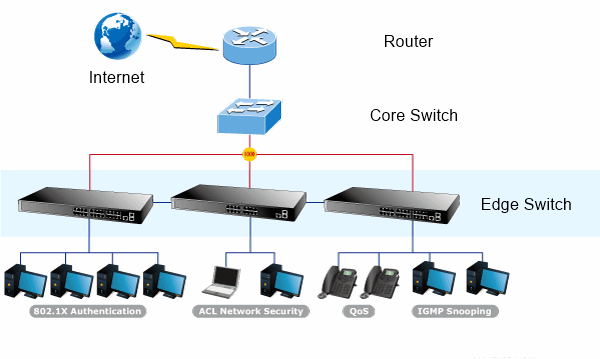
A core switch is a high-capacity switch generally positioned within the backbone or physical core of a network. Core switch is also regarded as a backbone device that is vital to the successful operation of a network: it serves as the gateway to a wide area network (WAN) or the Internet, so that you can use it to connect to servers, your Internet service provider (ISP) via a router, and to aggregate all switches. A core switch need to be powerful enough and have significant capacity to handle the load sent to it, which means it should always be a fast, full-featured managed switch.
In a public WAN, a core switch interconnects edge switches that are positioned on the edges of related networks. In a local area network (LAN), this switch interconnects work group switches, which are relatively low-capacity switches that are usually positioned in geographic clusters.
core-edge switch connectivity
How About an Edge Switch?
As the name indicates, an edge switch is a switch located at the meeting point of two networks. These switches connect end-user local area networks (LANs) to Internet service provider (ISP) networks. Referred to as access nodes or service nodes, an edge switch connects client devices, like laptops, desktops, security cameras, and wireless access points to your network. Edge switches for WANs are multiservice units supporting a wide variety of communication technologies, it also provides enhanced services such as virtual private networking support, VoIP and quality of service (QoS). Generally, smart switches and even unmanaged switches are valid options at the edge of your network. But for some downtime-sensitive applications or where security matters, a managed switch can also be equally used at the edge.
Core Switch/Edge Switch Selection: What Exactly Matters?
To select the appropriate switch for a layer in a particular network, you need to make clear specifications regarding current/future needs, target traffic flows and user communities.
1. Future Growth
Switches comes in different sizes, features and function, choosing a switch to match a particular network involves a solid network plan for any future growth. With that in mind, you would want to purchase a switch that can accommodate more than 24 ports, such as stackable or modular switches that can scale.
2. Performance
When selecting a switch for the access, distribution, or core layer, consider the ability of the switch to support the port density, forwarding rates, and bandwidth aggregation requirements of your network.
An edge switch needs to support features such as port security, VLANs, Fast Ethernet/Gigabit Ethernet, PoE and link aggregation. While a core switch also needs to support link aggregation to ensure adequate bandwidth coming into the core from the distribution layer switches. Also, a core switch support additional hardware redundancy features like redundant power supplies, and hot-swappable cooling fans. So there is no downtime during switch maintenance.
FS.COM Core Switch and Edge Switch Solution
FS.COM offers a large portfolio of Ethernet switches including 10GbE switch, 25GbE switch, 40GbE switch and 100GbE switch, each with different port configurations and moderate to advanced feature sets that tailored for enterprise networks and data centers. The core switch and edge switch in FS.COM are presented as follows.
Core Switch S5850-32S2Q, S5850-48T4Q, S5850-48S6Q, S5850-48S2Q4C, S8050-20Q4C, N5850-48S6Q, N8000-32Q, N8500-32C, N8500-48B6C
Edge Switch S3700-24T4S, S2800-24T4F, S3800-24T4S, S3800-48T4S, S3800-24F4S, S5800-8TF12S, S5800-48F4S
All these network switches are tested with the highest industry standard in rigorous environment, for more specifications, just reach out to us via sales@fs.com.

Monday, July 2, 2018

Why You Need a Managed 8 Port PoE Switch

Gigabit PoE switch, or power over Ethernet switch, has seen massive adoption these days by providing improved network flexibility and performance. A Gigabit PoE switch transmits both data and power supply simultaneously to network devices such as VoIP phones, Wireless AP and network cameras without changing existing Ethernet cabling structure, which in turn, greatly reduce the cabling complexity as well as the cost of installation and maintenance. These exists 8/10/16/24/48 port PoE switches with gigabit speed and essential managing functions, among which a 8 port Gigabit PoE switch is poised as a cost-effective choice for home and business use. Let’s see what we can achieve with a 8 port PoE switch.

8 Port PoE Switch: Managed or Unmanaged?

Like choosing a standard data switch, we’ll inevitably find ourselves in a dilemma: should we choose a managed or unmanaged Gigabit PoE switch? The answer is pretty easy and straightforward – a managed PoE switch is always better. Managed switches typically offers advanced security features and allows for administrators visibility and control. Besides, a managed PoE switch also offers higher level of manageability and control, so you’re able to program each port individually while keep the network operating at peak efficiency. This results significant saving on power and cost. Additionally, a managed Gigabit PoE switch is capable of configuring, managing and monitoring the LAN – setting/disabling the link speed, limiting bandwidth or grouping devices into VLANs.
gigabit poe switch

How to Use a Managed 8 Port PoE Switch?

Managed Gigabit PoE switch has become a preferable option for enterprise networks, with dramatically decreased price, expanded feature sets and improved ease of use. Experience from those who have dealt with a managed 8 port PoE switch also demonstrates that this is a journey well worth taking. You can use a managed 8 port PoE switch to creates VLANs and limit access to specific devices, to use Layer 3 routing capability and to remotely monitor network performance.
Common applications of a managed 8 port PoE switch includes the following aspects.
Connect IP Cameras, Wireless Access Points and IP Phones
To connect this PoE enabled device, you need to know the power consumption of these device, as well as a total power/ power per port of your PoE switch. For example, you have a managed 8 port PoE switch with a power budget of 250W with the maximum power consumption per port 30W. Assume to power an IP Camera network, you’ll need a total power per port of 30W. Then you can connect all the 8 ports with IP cameras with a total power consumption of 240W (within the budget of 250W).
Voice over IP phones Enterprise can install PoE VoIP phone, and other Ethernet/non-Ethernet end-devices to the central where UPS is installed for un-interrupt power system and power control system.
Wireless Access Points Museum, sightseeing, airport, hotel, campus, factory, warehouse can intall the WAP anywhere.
IP Camera Enterprise, museum, campus, hospital, bank can install IP camera without limits of install location – no need electrician to install AC sockets.
The key applications are illustrated as following.
8 port poe switch application
Connect Non-PoE Switches and Devices
One of the frequently asked question is that whether we can mix PoE and Non-PoE devices on the same PoE network. The answer is positive. PoE will only send power if it requested by the device. Otherwise the switch just interacts with it as if it were a regular switch. When connecting a managed 8 port PoE switch to non PoE compatible devices, a PoE splitter is commonly adopted – it delivers data and DC power through separate connections.
mix poe switch with non poe switch

FS.COM 8 Port PoE Switch Solution

Managed gigabit PoE switch has become a better choice if you ever anticipate advanced network features to meet business growth. A managed 8 port PoE switch is the best fit for SMB network and home use with relatively small traffic flow. FS.COM fully understands customer expectations and offers managed 8 port PoE switch with the price starting from $159. Besides, we also provide 24 port PoE switch and 48 port PoE switch to help future-proof your network and unleash the potential of your business. Feel free to contact us via sales@fs.com for more solutions.

Sunday, June 24, 2018

Network Switch Port Mirroring vs. Network TAP

Nowadays networks are carrying significant volumes of data at increasing speeds - it is getting more complex than ever. Consequently, network visibility is critical to monitor, manage and protect your network. So having access to inner working condition of the network is paramount to every network manager. Network TAP and network switch port mirroring provide direct access to the actual packets navigating across networks. If both options work, which is a better choice? And when should we choose one over the other? We try to address those issues here.

Basics of Network Switch Port Mirroring

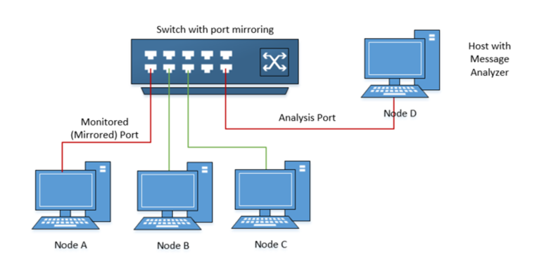
Network switch port mirroring is nothing new for us. It is performed by a mirror port - a software feature built into a network switch that creates a copy of selected packets passing through the device and sends them to a designated mirror port. It enables a network manager to configure or change the data to be monitored. Since the primary purpose of a network switch is to forward production packets, port mirroring data is often with a lower priority. Besides, switch port mirroring uses a single egress port to aggregate multiple links, so it is easily oversubscribed.
network switch port mirroring
Advantages
  • Low cost, using existing switch capabilities.
  • Remotely configurable through the network.
  • Captures intraswitch traffic.
Disadvantages
  • Drops packets on heavily used full-duplex links.
  • Filters out Physical Layer errors.
  • May burden the switch’s CPU to copy data.
  • May change frame timing, altering response times and slowing network performance.

Network TAP Explanation

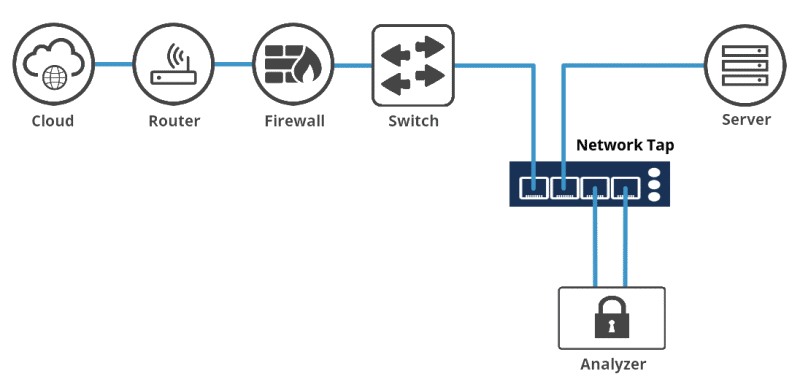
A network TAP (Test Access Point) is a passive device that used to directly connect to the cabling infrastructure. Instead of two switches or routers connecting directly to each other, the network TAP is put between the two devices and all data flows through the TAP. With an internal splitter, the TAP creates a copy of the data for monitoring while the original data continues unimpeded through the network. In this case, packet of any size can be copied by TAP – it thus eliminates any chance of oversubscription. Once the data is TAPed, the duplicate copy can be used for any sort of monitoring, security, or analytical use.
network tap
Advantages
  • Captures send and receive data streams simultaneously, eliminating the risk of dropped packets.
  • Provides full visibility into full-duplex networks.
  • Captures everything on the wire—including Physical Layer errors—even when the network is saturated.
Disadvantages
  • Requires the purchase and installation of additional hardware.
  • Analysis device may need dual-receive capture interface.
  • Only captures data between network devices; can’t monitor intra-switch traffic.

Network Switch Port Mirroring vs. Network TAP: Differences?

The differences concerning port mirroring and network TAP is summarized as following.
  • TAPs create an exact copy of the bi-directional network traffic at full line rate, providing full fidelity for network monitoring, analytics and security. While network switch mirror ports are easily oversubscribed – resulting in dropped packets, which leads to inconsistent results for monitoring and security purposes.
  • Passive TAPs provide continuous access to traffic and require no user intervention or configuration once installed. Network switch port mirroring, however, can have a negative performance impact on the switch itself, sometimes affecting network traffic.
  • Network TAPs allow for traffic monitoring for a particular segment. But port monitoring traffic output can change from day to day or hour to hour – resulting in inconsistent reporting. When configured mirror ports incorrectly, it will impact network performance.
  • TAPs are usually protocol transparent – be it carried in the traffic or if it is IPv4 or IPv6. All traffic is passed through a passive TAP.
  • Network switch mirror ports are limited in number compared to the number of ports that may require monitoring, and consume ports that could otherwise be carrying production traffic.

Port Mirroring vs. Network TAP: When to Use Which?

Simply put it, TAPs are a key component and should be applied in any system demanding 100% visibility and traffic fidelity. And whenever traffic volumes are moderate to high, it’s better to deploy network TAPs. Note that inserting a TAP into an existing network link requires a brief cable disconnect, so TAPs are typically installed during a maintenance window, or to install it during the early design phase.
On the other hand, network switch port mirroring works best for ad hoc monitoring of low volumes of data in locations where TAPs have not been installed. It still represent the only means for accessing certain types of data, such as data crossing port-to-port on the same switch, remote locations with modest traffic that cannot justify a fulltime TAP, or traffic that stays within a switch that never reaches a physical link.

Conclusion

There is no doubt that both TAPs and network switch mirror ports can provide valid access to data if used correctly. Choose TAPs when you can justify the cost, while opt for port mirroring where you must. FS.COM is backed by a professional and experienced team to provide solutions for network TAPs and Ethernet switch, for more details, feel free to contact us via sales@fs.com.

Monday, June 4, 2018

QSFP + zu SFP + Adapter (QSA Adapter) vs. QSFP + zu SFP + Breakout-Kabel

Leute fragen häufig nach machbaren Lösungen zwischen 10G und 40G Servern. QSFP + Breakout-Kabel wie QSFP + zu 4 SFP + -Kabeln und MTP zu 4 LC-Kabelbaumkabel sind die gebräuchlichsten Geräte für die Verbindung zwischen QSFP + -Ports und SFP + -Ports. Vor kurzem hat Cisco jedoch eine neue Art von Produkt auf den Markt gebracht: das Modul QSFP + zu SFP + Adapter (QSA Adapter), das eine reibungslose Migration auf 40 Gigabit Ethernet ermöglicht. Ist es eine bessere Lösung für die Migration von 10G nach 40G? Sollte ich den QSA-Adapter oder das 40G QSFP + Breakout-Kabel verwenden? Dieser Artikel beantwortet die obigen Fragen und gibt Ihnen einige Vorschläge.

QSA Adapter - Ist es eine bessere Lösung für 40G Migration?

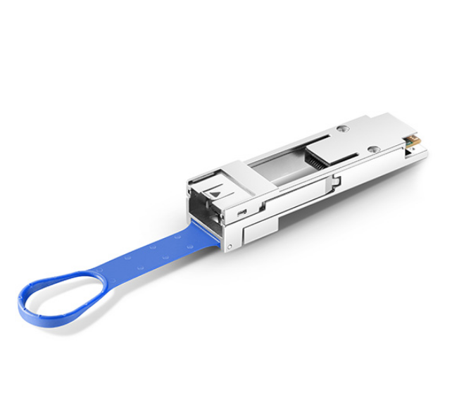
Der QSFP + zu SFP + Adapter (QSA Adapter), spezifiziert von Cisco, ist das Modul im QSFP + Formfaktor mit einer Buchse für SFP + Kabelstecker auf der Rückseite (siehe unten). Wenn Sie den QSFP-Port mit einem SFP + -Port verbinden, fungiert der QSA-Adapter normalerweise als Schnittstelle für SFP + / SFP-Kabel. Das bedeutet, dass Sie eine SFP + / SFP-Optik, die an einem 10-Gbit / s-Port dieses Moduls arbeitet, effektiv einstecken und das Modul in einen QSFP-Port-Käfig einsetzen können, um den 40G-Ethernet-Übergang zu realisieren. Der QSA-Adapter gewährleistet die problemlose Verbindung zwischen 40-Gigabit-Ethernet-Adapter und 10-Gigabit-Hardware mit SFP + -basierter Verkabelung. Sobald der QSA-Adapter im Jahr 2016 herauskam, wurde er bald als die effektive Lösung für die Umwandlung von 40G-Ports in die 10G-Ports angesehen.
QSA Adapter

Übersicht über die 40G QSFP + Breakout-Kabel

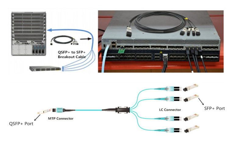
Benutzer verwenden normalerweise entweder die Breakout-Kabel QSFP + bis 4 SFP + oder MTP-zu-LC-Kabel, um den Downlink-40G-Anschluss des ToR (Top of Rack) -Zugriffsschicht-Switches in den 4x10G-Fan-Out-Modus zu konvertieren und dann an den 10G-Gehäuse-Serverport anzuschließen. QSFP + zu SFP + Breakout-Kabel, einschließlich des Direct-Attach-Kupferkabels (DAC) und des aktiven optischen Kabels (AOC) besteht aus einem QSFP + -Anschluss an einem Ende und vier SFP + -Anschlüssen am anderen Ende. Die Kabel verwenden leistungsstarke integrierte serielle Duplex-Datenverbindungen für die bidirektionale Kommunikation auf vier Verbindungen gleichzeitig.
QSFP+ Breakout-Kabel
Während das MTP-zu-LC-Kabelbaumkabel ein MTP-Kabel an dem einen Ende und vier LC-Anschlüsse an dem anderen Ende aufweist. Diese Art von Kabel wird empfohlen, um im selben Rack innerhalb der kurzen Entfernung verwendet zu werden. Das Bild oben zeigt die direkte Verbindung zwischen den QSFP + Transceivern und den SFP + Transceivern unter Verwendung des MTP zu LC Kabelbaumkabels.

QSA-Adapter oder QSFP + Breakout-Kabel?

In diesem Teil werde ich einen Vergleich zwischen QSFP + zu SFP + Adapter-Modulen (QSA Adapter) und QSFP + Breakout-Kabeln hinsichtlich Kosten, Leistung und Kompatibilität anstellen.
(1) Kosten - QSFP+ Breakout Kabel gewinnt
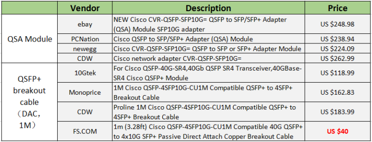
Das QSA-Adaptermodul ist nicht durch Multi-Source-Agreement (MSA) zertifiziert, sondern ein einziges Quellparadigma, das von wenigen Anbietern definiert wird. Der einzige Anbieter besitzt sein Patent, daher sind die QSA-Adapter auf dem Markt ziemlich teuer. Nichtsdestotrotz unterstützen QSFP + Breakout-Kabel, die vom MSA-Standard abgedeckt werden, Kupfer- und optische Verbindungen, die viel billiger sind als QSA-Adapter. Der Kostenvergleich zwischen QSA-Adapter und QSFP + Breakout-Kabel (DAC, 1m) ist in der folgenden Tabelle aufgeführt.
QSA-Adapter oder QSFP+ Breakout-Kabel
(2) Leistung
Mit dem QSA-Adapter können Benutzer SFP + / SFP-Optiken verwenden, um mit einer einzigen 10G-Verbindung eine Verbindung zur 40-Gbit / s-Datenrate herzustellen. Allerdings gibt es den QSA-Adapter nur in 10G-40G-Geschwindigkeit, was auch die Gründe für die Unbeliebtheit des Marktes erklärt. QSFP + bis 4 SFP + Breakout-Kabel teilen den 40G-Kanal in einen 4x10G-Kanal auf, der viermal mehr Daten überträgt als der QSA-Adapter.
(3) kompatibler Schalter und SFP/SFP + -Module
QSA-Adapter sind laut Cisco in einer 40-Gigabit-Ethernet-Kompatibilitätsmatrix verfügbar. Cisco SFP / SFP + -Transceiver, die an die QSA-Adapter angeschlossen werden können, werden als Cisco 10GBASE-SR-, LR-, ER-, ZR-, DWDM SFP + -, FET-10G- und 10G SFP + -Kabel sowie als SFP (1000BASE-T, SX, LX, EX, ZX). Wie für die Breakout-Kabel QSFP + zu SFP + haben verschiedene Hersteller unterschiedliche kompatible Probleme. Denken Sie daran, dass Sie die zuverlässigen Glasfaser-Transceiver-Hersteller finden sollten.
Erinnerung:
- Bevor Sie die QSA-Adapter oder die QSFP + Breakout-Kabel verwenden, um einen 40-Gigabit-Ethernet-Port mit einem 10-Gigabit-SFP + -Port zu verbinden, müssen Sie den Fan-Out-Modus Ihrer Geräte aktivieren.
- Nicht alle 40G-Karten und -Switches können in den 4x 10Gb-Modus aufgeteilt werden, z. B. unterstützen die Mellanox QSFP-Karten nicht den Breakout QSFP bis SFP +, aber ihre Switches können.
- Mit den QSA-Adaptern können Sie die SFP + -Module direkt in einem QSFP + -Port verwenden, aber Sie können die QSFP + -Optikkabel nicht in einem QSA-Setup verwenden.
Die Telecom-Industrie wurde schnell modifiziert. Daher ist es kostengünstiger, zusätzliche Investitionen in Hochgeschwindigkeits-Switches anstelle von Breakout-Kabeln und teuren QSA-Adaptern zu tätigen.

Fazit

Sowohl die QSFP + Breakout-Kabel als auch die QSA-Adapter ermöglichen eine reibungslose Migration auf das 40 Gigabit Ethernet. Mit diesen Optiken können Sie vorhandene 10G SFP + -Kabel, optische Transceiver und Switches beim Upgrade auf 40G-Ethernet wiederverwenden. QSFP+ Breakout-Kabel gelten als die kosteneffektivsten und zuverlässigsten Lösungen für die meisten Situationen, aber QSA-Adapter sind für die Anwendung mit einer einzigen 10G-Verbindung vorzuziehen.

Monday, May 28, 2018

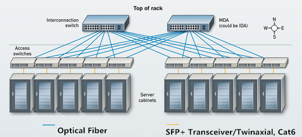
SFP+ Fiber vs SFP+ Twinax Kabel vs 10GBASE-T, Welche für 10G wählen?

Wenn Sie den Server, den Speicher und die Einrichtung Ihres Rechenzentrums ausgewählt haben, wie verbinden Sie dann alles miteinander? Es besteht kein Zweifel, dass die Antwort "mit Kabeln" ist. Sehen wir uns die drei am häufigsten verwendeten Kabel an, die zum Verbinden der Server und des Speichers mit Switches in einem 10G-Netzwerk verwendet wurden. Sie sind SFP+-Transceiver-Module (verwendet mit LC-Faser-Patchkabel), SFP+-Kabel (DAC Twinax) und 10GBASE-T-Lösung. Welchen solltest du wählen? Lass uns gemeinsam die Antwort finden!
SFP+ Faserlösung

SFP+ Faserlösung

Diese Verbindungsmethode erfordert zwei Dinge auf jedem Gerät: 10G steckbarer SFP+-Transceiver und Glasfaser-Patchkabel. Sobald diese auf beiden Geräten (Server und Switch) vorhanden sind, können Sie die Patchkabel auf beiden Seiten in den Transceiver einstecken. Diese SFP+-Transceiver-Module verwenden ungefähr 1 W pro Transceiver und haben eine Latenzzeit von weniger als 0,1 Mikrosekunden. SFP+-Transceiver sind in verschiedenen Ausführungen erhältlich, um Signale über Glasfaserkabel mit unterschiedlichen maximalen Entfernungen zu übertragen. Das am weitesten verbreitete billige SFP+-Modul ist 10GBASE-SR, das 300 Meter überspannen kann. Andere Arten können bis zu 100 Kilometer erreichen.
SFP+-Transceiver-Module
Vorteile: Diese Konnektivitätsmethode unterstützt sehr lange Glasfaserkabel, sodass Sie einen Server an einem Ende eines Datencenters mit einem Switch verbinden können, der mehrere Racks entfernt ist oder sogar am anderen Ende.
Nachteile: Pluggable Transceiver Teile sind ziemlich teuer.

SFP+-Kabel: DAC Twinax Kabel

SFP+ Direct Attach Kupfer Kabel (DAC) integriert Transceiver mit Twinax-Kabel in eine energieeffiziente, kostengünstige und latenzarme Lösung. Er verfügt an beiden Enden über SFP+-Anschlüsse, so dass keine teuren SFP+-Transceiver erforderlich sind. SFP+-Kabel verwenden nur 1,5Watt Leistung pro Port und führen nur ungefähr 0,25 Mikrosekunden Latenz pro Link ein. Dies macht es zu einer optimalen Lösung für die Übertragung mit hoher Bandbreite innerhalb kurzer Entfernungen, wie in energieeffizienten Rechenzentren.
SFP+-Kabel
Vorteile: Geringere Latenzzeiten, geringere Leistung und geringere Wärmeentwicklung.
Nachteile: Die Übertragungsdistanz beträgt normalerweise weniger als 10 Meter.

10GBASE-T Lösung: Cat6 Kupferkabel

Diese Option kommt Ihnen wahrscheinlich bekannt vor-wie die RJ-45-Anschlüsse und die Verkabelung, die Sie verwenden, um Ihren Laptop an eine normale Netzwerkbuchse anzuschließen. Der Unterschied besteht darin, dass Sie spezialisierte Netzwerkadapter mit Ports benötigen, die einen schnelleren 10G-Durchsatz unterstützen. Cat6-Kabel haben mehr einzelne Kupferdrähte, die fester verdrillt sind und eine bessere Abschirmung haben, um Störungen von außen zu vermeiden. Sie kosten mehr als Cat5, sorgen aber für eine bessere Signalkommunikation, was eine Geschwindigkeit von bis zu 10G erfordert. Cat6-Kupferkabel verwenden 5 Watt Leistung pro Port und führen ungefähr eine Latenz pro Link ein, die viel höher ist als bei SFP+ -Optiken und SFP+.
10GBASE-T Lösung
Vorteile: Längere Entfernung-100 Meter. Abwärtskompatibilität zu 1 Gigabit Ethernet oder 100 Megabit Ethernet.
Nachteile: Höhere Latenz, höhere Leistung und höhere Wärme. Nicht viele Datencenter-Switches unterstützen 10GBASE-T-Ports.

Fazit

Vita Unterschiede dieser drei 10G Verkabelungslösungen sind in der folgenden Tabelle aufgeführt. Entsprechend Ihrer Forderung, den richtigen zu wählen.
SFP+ Fiber vs SFP+ Twinax Kabel vs 10GBASE-T
Wenn Sie zwischen SFP+ Glasfaser und SFP+-Kabel im Vergleich zu 10GBASE-T wählen müssen, sollte die Entscheidung auf Ihre Bedürfnisse abgestimmt sein. SFP+ DAC passen besser zu den Anforderungen und neuen Trends des heutigen Rechenzentrums. 10GBASE-T wird eine bessere Wahl für die Verkabelung sein, da die Nachfrage nach Bandbreite akuter wird. Für Geräte, bei denen der Stromverbrauch und die Latenzzeit entscheidend sind, könnte SFP+ besser geeignet sein. Wenn jedoch Kosten, Flexibilität und Skalierbarkeit wichtiger sind, sollten Sie 10GBASE-T in Erwägung ziehen. Beide sollten einen wichtigen Platz in der Zukunft des Netzwerkdesigns und der Best Practices finden.

Monday, May 14, 2018

LWL-Kabel: Multimode Fiber Oder Single Mode Fiber

Vor kurzem, LWL-Kabel wird immer beliebter in der Telekommunikation wegen seiner großen Bandbreite, schnelle Geschwindigkeit, Fernübertragung und niedrige Kosten. Single Mode Fiber und Multimode-LWL-Kabel sind in vielen Netzwerken wichtig, um optische Signale zu übertragen. Obwohl Sie das gleiche Funktionsprinzip und Funktionen haben, hat jeder von Ihnen Ihre eigenen vor-und Nachteile.

Single Mode Fiber und Multimode Fiber Übersicht

Personen, die mit optischen Netzwerken arbeiten, können mit Glasfaserkabeln vertraut sein. Und Sie können wissen, die grundlegende Struktur und Unterschiede zwischen Multimode Fiber und Single Mode Fiber. Hier ist eine einfache Tabelle mit den grundlegenden Kenntnissen von Ihnen.
single mode fiber and multimode fiber
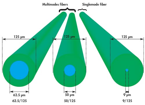
Von der Tabelle, die wir sehen können, hat Multimode-Fiber einen größeren Kerndurchmesser. Und es hat mehrere Übertragungsarten, aber Sie sind nur für Kurzstreckenverbindungen geeignet. Während Single-Mode-LWL-Kabel hat einen kleinen Kerndurchmesser, durch die nur ein Modus wird in der Regel 1310 oder 1550nm zu verbreiten. Aus diesem Grund sind diese Kabel oft in der Fernübertragung durch seine weniger Dispersion eingesetzt. Das folgende ist ein direkt-Anzeigebild zeigt die Durchmesser Unterschiede zwischen Single-Mode-LWL-Kabel-und Multimode-Glasfaserkabel.
single mode fiber vs multimode fiber

Vor-und Nachteile von Single Mode Fiber

Wie oben erwähnt, ist Single-Mode-LWL-Kabel besser geeignet für lange Läufe Anwendungen im Vergleich mit Multimode-Glasfaserkabel. Mit Ausnahme dieser, Single-Mode-LWL-Kabel hat auch andere drei Vorteile.
  • erhöhen Sie die Bandbreitenkapazität.
  • begrenzte Datenstreuung und externe Interferenzen. Der Single-Input-Modus ermöglicht SMF die Lichtstreuung zu begrenzen, die wiederum reduzieren Lichtabfall und erhöhen Datenübertragungs Daten.
  • schnelle Übertragungsgeschwindigkeit. Single-Mode-LWL-Kabel kann die Datenübertragung Geschwindigkeit bis zu 10 Gbps.
Jede Münze hat zwei Seiten. Single-Mode-Glasfaserkabel hat auch Nachteile. Die eine ist die Kosten. Obwohl es eine bessere Leistung in Long-Runs-Übertragung als Multimode-LWL-Kabel, Single-Mode-Glasfaserkabel oft mehr Kosten.

Vor-und Nachteile des Multimode-LWL-Kabel

Mit einem größeren Faser-Kern und gute Ausrichtung Toleranzen, Multimode-Faser-Kabel und Komponenten sind weniger teuer und sind leichter zu arbeiten mit anderen optischen Komponenten wie Glasfaser-Anschluss und Fiber-Adapter, im Vergleich mit Single-Mode-Glasfaserkabel. Darüber hinaus bietet Multimode-LWL-Kabel auch hohe Geschwindigkeit und hohe Bandbreite über kurze Strecken. Und Sie können mehrere optische Signale gleichzeitig übertragen.
Allerdings, Multimode-Fiber hat eine hohe Streuung und Dämpfungs Geschwindigkeit, die Qualität der optischen Signale wird reduziert, da die Übertragungsstrecke wird immer länger. Daher wird Multimode-LWL-Kabel häufig in Daten-und Audio/Video-Anwendungen in LANs verwendet.

Welche zu wählen, Single Mode Fiber-oder Multimode Fiber?

Besitzen, um Ihre eigenen Eigenschaften, Single-Mode-Glasfaserkabel und Multimode-Faser-Kabel haben verschiedene Anwendungsbereiche. Auf der Grundlage des Übertragungs-und Bereitstellungs Budgets ist das Multimode-LWL-Kabel, wenn der Übertragungsabstand weniger als 2km beträgt, besser, da es weniger teure optische Transceiver und andere Komponenten benötigt. Und wenn der Abstand über 2km ist, wird Single-Modus-Faser sein.