Friday, May 19, 2017

DWDM Topology Design: How to Make it Right?

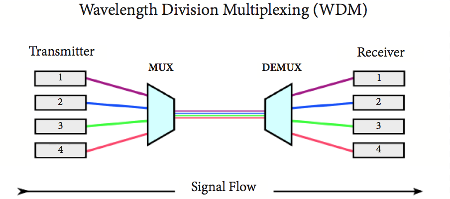
Network expansion spurs the demand for faster data transmission and higher capacity over the network. In this case, DWDM emerges as a cost-effective solution to handle these issues, working efficiently to combine multiple wavelengths together and sent them over one single fiber. With the ability to carry up to 140 channels theoretically, higher capacity can be achieved by DWDM technology. This article guides you through some basics of DWDM topology.
Common DWDM Topology Overview
DWDM networks are grouped into four major topological configurations: DWDM point-to-point with or without add-drop multiplexing network, fully connected mesh network, star network, and DWDM ring network with OADM nodes and a hub. The requirements of each DWDM topology differ, and based on various application, it may involve different optical components. Besides these four common DWDM topology, there also exists hybrid network topology, consisting of stars and/or rings that are interconnected with point-to-point links.
Configurations of DWDM Topology
This section illustrates the four basic DWDM topology configurations, help to understand the major differences and applications of them.
Point-To-Point Topology
Point-to-point topology is typically found in long-haul transport, which demands for ultra high speed (10-40Gb/s), ultra high aggregate bandwidth, high signal integrity, great reliability, and fast path restoration capability. The transmitter and receiver within this DWDM topology can be several hundred kilometers away, and the number of amplifiers between the two end points is generally less than 10. Together with add-drop multiplexing, point-to-point DWDM topology enables the system to drop and add channels along its path. A DWDM point-to-point system includes lasers, an optical multiplexer and demultiplexer, fibers, optical amplifiers, and an optical add-drop multiplexer.
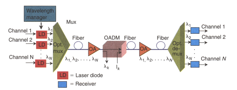
point-to-point dwdm topology
Ring-Configuration Mesh and Star Networks
Basically, a DWDM ring network includes a fiber in a ring configuration that fully interconnects nodes. Two fiber rings are even presented in some systems for network protection. This ring DWDM topology is commonly adopted in a local or a metropolitan area which can span a few tens of kilometers. Many wavelength channels and nodes may be involved in DWDM ring system. One of the nodes in the ring is a hub station where all wavelengths are sourced, terminated, and managed, connectivity with other networks takes place at this hub station. Each node and the hub have optical add-drop multiplexers (OADM) to drop off and add one or more designated wavelength channels. As the number of OADMs increases, signal loss occurs and optical amplifier is needed here.
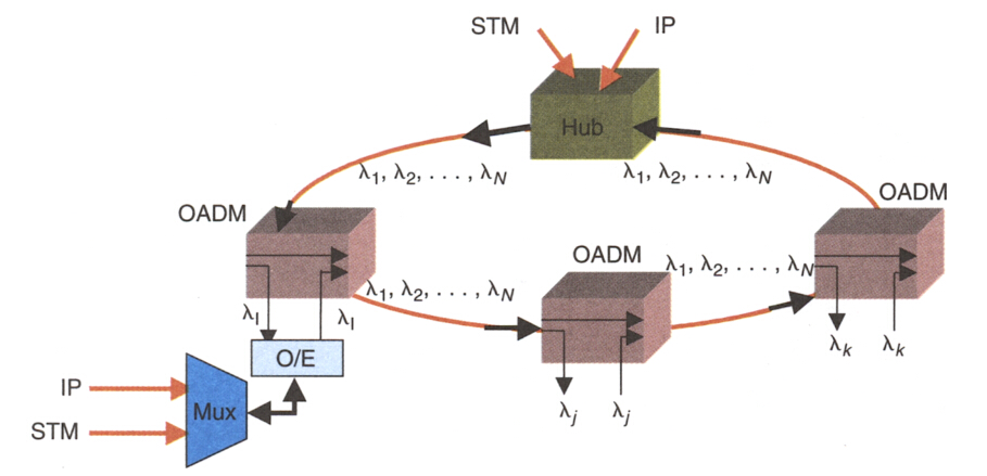
dwdm ring network
In the ring DWDM topology, a hub station works to manage channel assignment so that a fully connected network of nodes with OADM is accomplished. The hub also makes it possible to connect other networks. A DWDM mux/demux can be connected to an OADM node to multiplex several data sources. The following picture demonstrates a simple DWDM ring topology with a hub and two nodes (A and B).
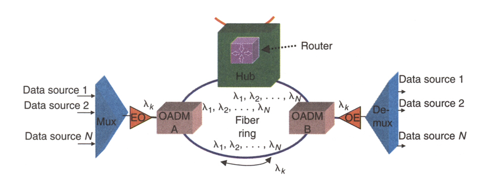
dwdm ring topology with hub
Transmit and Receive Directions of DWDM Hub
In the previous part, we’ve mentioned DWDM hub, which serves as a very essential parts in a DWDM system. Here we further explain the transmit and receive direction of a DWDM hub, proving system solutions for your reference.
Transmit Direction
A DWDM hub accepts various electrical payloads, such as communications transport protoco/Internet Protocol (TCP/IP), asynchronous transfer mode (ATM), STM, and high-speed Ethernet (l Gb/s, 10 Gb/s). Each traffic type (channel) is sent to its corresponding physical interface, where a wavelength is assigned and is modulated at the electrical-to-optical converter. The optically modulated signals from each source are then optically multiplexed and launched into the fiber.
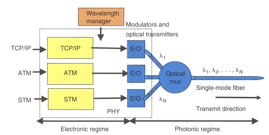
dwdm hub in the transmit direction
Receive Direction
When a hub receives a WDM signal, it optically demultiplexes it to its component wavelengths (channels) and converts each optically modulated signal to a digital electrical signal. Each digital signal then is routed to its corresponding electrical interface: TCPIIP, ATM, STM, and so on However, that each channel requires its own clock recovery circuitry because all channels may be at different bit rates.
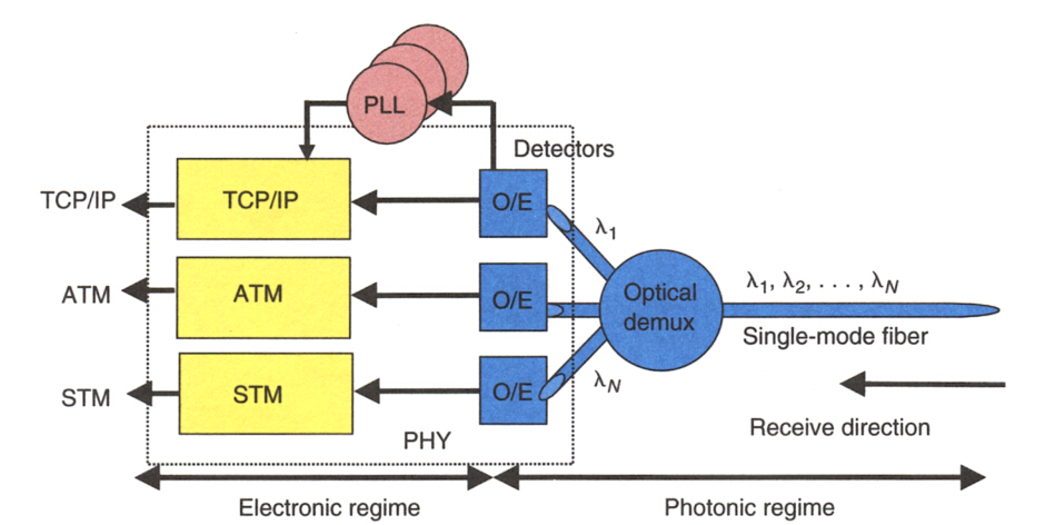
dwdm hub in the receive direction
Conclusion
The network topology of your DWDM system depends on various factors, including the number of nodes, maximum traffic capacity, scalability, number of fiber links between nodes and so on. Attentions also should be attached to the network components involved in the DWDM system. Hope this article could help to get more understanding towards DWDM technology.
Sunday, May 14, 2017

IP/WDM vs. IP/OTN: Which One to Choose?

The unceasingly demand for Internet-based services makes carrier IP networks a more critical social infrastructure. Operators are required to offer higher speeds, larger capacities and higher reliability network. There emerge two solutions to tackle this issue: IP/WDM and IP/OTN. IP/WDM consists of core routers connected directly over point-to-point WDM links, whereas IP/OTN connects the core routers through a reconfigurable optical backbone (OTN) consisting of electro-optical cross-connects (OXCs) interconnected in a mesh WDM network. This article guides you to choose between them.
Basics of WDM Technology
WDM technology is nothing new for us since it is rather prevalent especially for long haul data transmission. Its ability to provide potentially unlimited transmission capacity remains to be the most featured benefits. Either by simply upgrading the equipment or by increasing the number of lambdas on the fiber, network capacity can be obtained. It is the best choice for applications where channel density/bandwidth is of high priority. Aside from the bandwidth advantage, it also possesses these compelling merits.
wdm technology
  • Transparency—Being a physical layer architecture, WDM can transparently support both TDM and data formats such as ATM, Gigabit Ethernet, ESCON, and Fibre Channel with open interfaces over a common physical layer.
  • Scalability—WDM can leverage the abundance of dark fiber in many metropolitan area and enterprise networks to quickly meet demand for capacity on point-to-point links and on spans of existing SONET/SDH rings.
  • Dynamic provisioning—Fast, simple, and dynamic provisioning of network connections enable high-bandwidth services in days rather than months.
OTN Network Explanation
ITU-T defines OTN as a set of optical network elements (ONE) connected by optical fiber links, being able to provide functionality of transporting, multiplexing, switching, management, supervision and serviceability of optical channels carrying client signals. OTN was designed to optimize existing resources of a transport network. It is a digital wrapper that provides an efficient and globally accepted way to multiplex different services onto optical light paths. The advantages of OTN consist of the following aspects.
OTN network
  • It has the facility to work with DWDM and SDH equipment within banded or mesh networks.
  • Transmits SDH services, without termination of the signal at each network element, the signal transport is transparent including the clock and byte header.
  • Easily combine multiple networks and services on a common infrastructure entirely in the optical domain and transparent to the format and the speed of the signal carrying client, allowing you to create a multi-platform client.
  • The OTN services offering is gully software programmable via a single line card, so that the protocols, connectivity and functionality can be reprogrammed remotely as they change services or customers.
IP/WDM vs. IP/OTN: How to Choose From?
Before we go any further, let’s first look at the basic architecture of each. In the IP/WDM architecture, core routers are connected directly over point-to-point WDM links, whereas in the IP/OTN architecture, they are connected through a reconfigurable optical backbone (OTN) consisting of electro-optical cross-connects (OXCs) interconnected in a mesh WDM network. (See the figure below). We assume that each Point of Presence (PoP) or CO (Central Office) consists of four IP routers. It is clear that in IP/WDM, the routers are connected directly to the WDM systems, which connect them to neighboring PoPs. On the other hand, in IP/OTN, there is an intermediate element (OXC) which is responsible for connecting IP routers from different PoPs.
IP over WDM vs. IP over OTN
The major differences of these two approaches include the following aspects:
1. In IP/WDM, traditional transport functions such as switching, grooming, configuration and restoration are eliminated from the SONET/SDH layer and moved to the IP layer which is supposed to be enhanced by MPLS. Alternatively, the optical layer is the one that deals with the aforementioned, exploiting the intelligence of OXCs.
2. IP/OTN solution is more scalable than IP/WDM since the core of the network is based on the more scalable OXCs rather than IP routers.
3. IP/OTN is more flexible to traffic changes than IP/WDM.
4. IP/OTN, the optical transport layer provides the restoration services in a fast and scalable way (optical shared mesh restoration), whereas in IP/WDM restoration is achieved by IP rerouting which is a slow process and may lead to instability in the network.
5. When comparing the cost, IP/WDM appears to be a more cost-prohibitive solution than the IP/OTN architecture. Furthermore, as years go by and total traffic increases, the cost difference between both architectures is more severe.
Conclusion
From what we presented in the article, it is clear that IP/OTN is a more cost-efficient solution. And the savings increase rapidly with the number of nodes and traffic demands between them. Furthermore, IP/OTN is superior over IP/WDM in other qualitative terms like scalability, availability and resiliency. FS.COM endeavors to provide cost-effective and feasible optical network solutions. For more information, please visit www.fs.com.

Wednesday, May 3, 2017

CWDM Network: Technology Overview and Common Applications

Fiber exhaust is an inevitable problem constantly faced by carriers since the demand for higher speed bandwidth never ceases. The ever-improving wavelength division multiplexing (WDM) technology nowadays is increasingly used to boost network capacity, enabling carriers to deliver more services over their existing fiber infrastructure. CWDM, as one form of the mature WDM technologies, is a perfect fit for access networks and metro/regional networks. This article addresses the CWDM fundamentals and its common applications, and how CWDM helps to maximize network capacity effectively.
CWDM Technology at a Glance
Coarse wavelength division multiplexing (CWDM) came into prominence as a cost-effective alternative to maximize network capacity in the access, metro and regional network segments. It gains in more popularity in area with a relatively moderate traffic growth due to its simple deployment and low cost. ITU-T G.694.2 defines 18 wavelengths for CWDM transport ranging from 1270 to 1610 nm, spaced at 20 nm apart. But 8 wavelength in the 1470-1610nm band is mostly used since there exist high attenuation in the 1270-1450 nm band. This technology shines out in access network deployments by obtaining the advantages of flexible add-drop capacity and network design simplicity.
CWDM wavelength
Common Applications of CWDM
After going through the basics of CWDM technology, this section will further explain its common applications. CWDM is primarily deployed in two areas: metropolitan and access networks. Let’s see how they could benefit from applying it.
Fiber Exhaust Relief
Fiber exhaust appears to be a severe problem that carriers endeavor to solve, especially for some metropolitan networks where data traffic increases continuously. Adding CWDM to the original optical network presents a cost-efficient and simple approach to this problem. In this case, carriers can add new services over a existing single optical fiber, while not interrupting service for existing customers. This solution is ideally suited for carriers that desires to increase the already installed network capacity without new fiber construction.
CWDM increases capacity
Enterprise LAN and SAN Connection
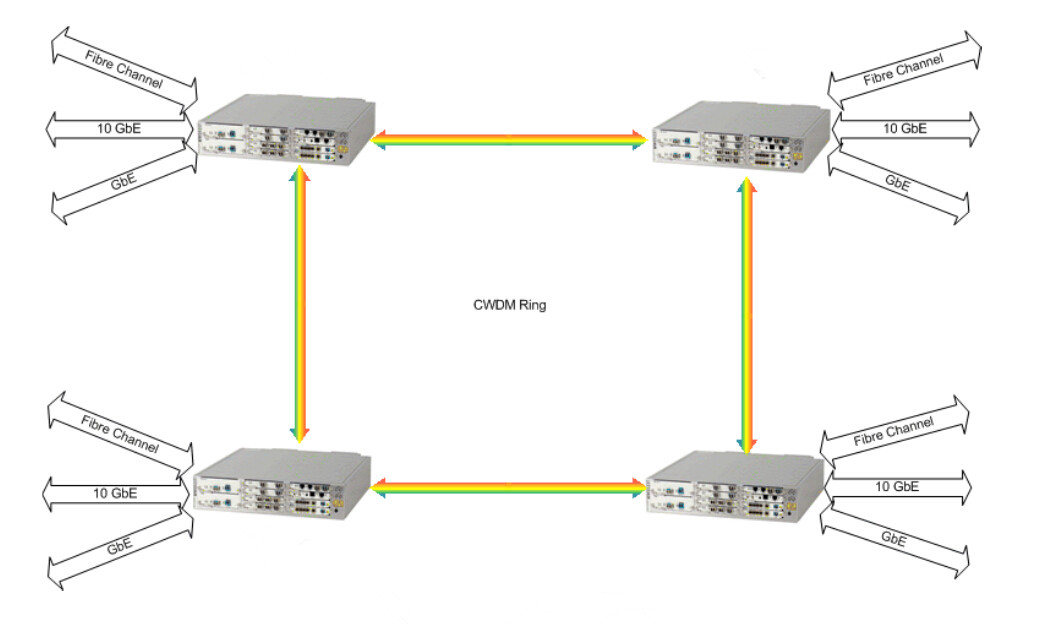
When interconnecting geographically dispersed Local Area Networks (LANs) and Storage Area Networks (SANs), CWDM rings and point-to-point links offer an optimum option. It is beneficial to integrate multiple Gigabit Ethernet, 10 Gigabit Ethernet and Fiber Channel links over a single fiber for CWDM point-to-point applications or for ring applications.
CWDM ring
Adoption in Metro Networks With Lower Cost
4 channel CWDM system offers an ideal solution for smaller metro/regional markets which demand for moderate traffic growth. This configuration can expand the available capacity four times over an existing network, enabling less deployment cost than the commonly adopted 8 channel system. Meanwhile, the scalability of this 4 channel system also allows carriers to upgrade to 8 channel systems when the need occurs.
Central Office to Customer Premise Interconnection
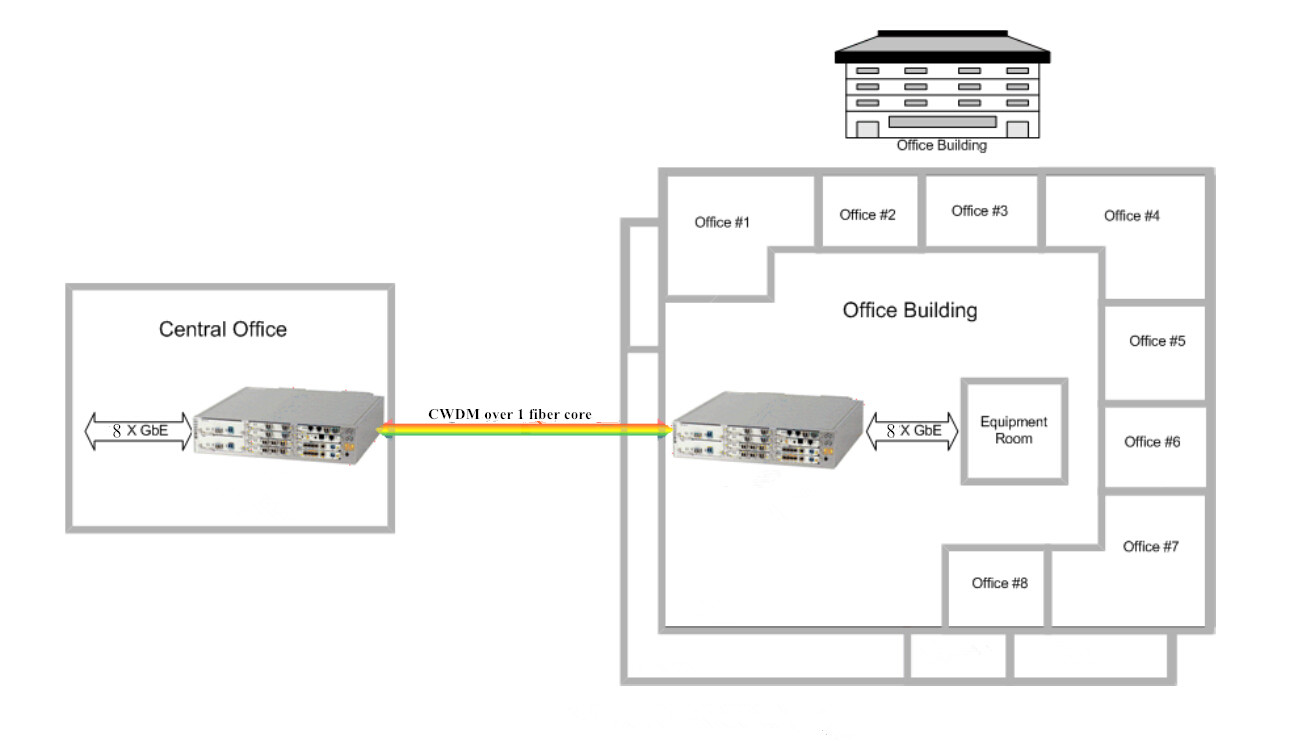
Coarse WDM system is also well-fitted for metro-access applications such as Fiber to the Building (FTTB). Let’s take the most widely used 8 channel CWDM network for example, it is capable of delivering 8 independent wavelength services from the Central Office (CO) to multiple business offices located in the same building.
CWDM for FTTH application
Combining With PON
Passive Optical Network (PON) is a point-to-multipoint optical network to deliver bandwidth to the last mile. It is cost-effective because it uses passive devices (splitters for example) instead of expensive active electronics. The issue exists in PON is that the amount of bandwidth they can support is rather limited. Since CWDM serves to multiple bandwidth, when combining it with PON, each additional lambda becomes a virtual point-to-point connection from a central office to an end user. If one end user in the original PON deployment needs his own fiber, adding CWDM to the PON fiber creates a virtual fiber for that user. Once the traffic is switched to the assigned lambda, the bandwidth taken from the PON is now available for other end users, so the access system can maximize fiber efficiency.
Conclusion
CWDM has clearly become the preferred method for increasing the bandwidth of metro/regional and optical access networks quickly, simply and at lowest cost. And it has proven to be sufficiently robust and reliable for upgrading the optical network to accommodate future growth. Hope this article could help to get a better understanding of coarse WDM technology.