Friday, December 29, 2017

48-Port 10GE Switch Selection: What Is the Right Choice?

The advent of big data, virtualization and cloud computing are pushing higher speed network adoption. As such, data center networks are going through a profound change - in which 40GE has become ubiquitous and 10GE a must. Network managers have reaped great benefits by deploying 10G Ethernet switch at the edge of the large professional network, which makes 10G SFP+ switch a choice for speed and productivity. In the midst of various 10G Ethernet switch, a 48-port 10GE switch is considered as an optimal solution for handling data traffic that delivers great scalability. Then how to choose the right 48-port 10GE switch? We’re going to explore it in this article.

Why Do I Need a 48-Port 10GE Switch?

10G Ethernet switch is a cost-effective solution compared to multiple Gigabit Ethernet ports, while delivers substantially better throughput and latency. It is already well established in IT industry and we’ve seen massive adoption of 10G infrastructure. Density, power and cooling of 10G SFP+ switch are key motivators for deployment of data center network. With compelling improvement in bandwidth, port density, latency and power consumption. 10G SFP+ switch has become the interconnect of choice for latency sensitive application with enhanced reliability and network performance. 10G Ethernet switch comes into various port configuration, and a 48-port 10GE switch is the most future-proofing one with abundant application in business oriented network. It increases the total available bandwidth, the reduced power consumption in cables and switch ports, and overall reduction in infrastructure costs.

48-Port 10GE Switch Selection: What Is the Right Choice?

Common 48-Port 10GE Switch Comparison

As the need for 48-port 10 Gigabit switch spurring, vendors also compete to offer 10G Ethernet switch with advanced function and decreased cost. Here we compare some commonly seen 48-port 10GbE switch along with FS.COM N5850-48S6Q 48-port 10GE switch, including parameters about their port combination, switching capacity, latency, power consumption and 48-port 10Gb switch price.

Model
Edge-core AS5712-54X
Cisco WS-C3850-48XS-S
Dell Networking S4048-ON
HPE 5900AF (JC772A)
N5850-48S6Q
SFP+ Ports
48
48
48
48
48
QSFP+ Ports
6
4
6
4
6
Switch Class
L2 and L3
L3
L2 and L3
L3
L3
Switching Capacity
720 Gbps
1280 Gbps
1.44Tbps full-duplex
1280 Gbps
1.44Tbps full-duplex
Latency
720 ns
-
600ns
-
680 ns
Max Power Drew
282 W
-
234.35 W
260 W
200W
Forwarding Rate
1 Bpps
909 Mpps
1080 Mpps
-
1 Bpps
Price
$5,095.00
$7,970 00
$7,475.96
$9522.52
$4,419.00

When selecting a 10G SFP+ switch, it all comes down to two things: application and budget. Your application of the 48-port 10GE switch partially determines several factors, such as port configuration, switching capacity, power consumption and switch class. The port configuration and speed are relative to switching capacity. So you have to consider the amount of traffic to run through this 48-port 10GE switch and select one that can accommodate all the data flow. Power consumption on the other hand is also very essential as it defines the operating cost in the long run, a power efficient switch can save you a great amount of money. All the 10G Ethernet switch in the table have very similar port combination and they are all L2/L3 switches. As for these 48-port 10Gb switch price, N5850-48S6Q has unsurpassed benefits over the others.

Deep Dive into FS.COM 48-Port 10GE Switch N5850-48S6Q

This 48-Port 10GE switch N5850-48S6Q is a 10G SDN switch, which is designed to meet the high-performance, availability, and network-scaling requirements of enterprise and cloud data centers. It provides full line-rate switching at Layer 2 or Layer 3 across 48 x 10GbE ports and 6 x 40GbE uplinks, delivering 1.44Tbps switching capacity for the most demanding applications. This 48-port 10GE switch can be used either as a Top-of-Rack switch, or as part of a 10GbE or 40GbE spine-leaf fabirc. All ports support full L2/L3 features, IPv4/IPv6 and OpenFlow for high scalability and Software-defined Network (SDN) for ease of operation. Besides, N5850-48S6Q 48-Port 10GE switch delivers excellent low latency (680 ns) and power efficiency in a PHYless design. While support for advanced features, including MLAG, VxLAN, SFLOW, SNMP, MPLS etc, this 48-port 10G Ethernet switch is ideal for traditional or fully virtualized data center.

fs.com 48-port 10ge switch

Conclusion

48-port 10GE switch has made a great leap forward to satisfy the demand for increased network performance, reliability and scalability. The need for 10 Gigabit Ethernet spans all markets and business types, as technology marches forward, these 10G Ethernet switches will no doubt drop in cost and increase in capability. Equipped with higher level of hardware and software reliability design, FS.COM 48-port 10 Gigabit switch offers compelling reliability and scalability improvements. For more information, welcome to visit our site.

Sourcehttp://www.fiber-optic-tutorial.com/48-port-10ge-switch-select-right.html

Thursday, December 21, 2017

Smart Switch: A Wise Choice for SMB Networks

Ethernet network switch marks the backbone of your enterprise network, with which you can connect multiple core devices like routers, printers, PCs and other hardware. There exist a dazzling array of network switches with various feature sets and functions. With regard to management options, there are primary three categories of switches: unmanaged switch, smart switch and managed switch. Among which smart switch has ranked as a moderate choice for better regulating business network – as a perfect mix of essential functions and affordability. If you’ve outstripped your unmanaged switch but don’t expect for a more advanced managed switch, it’s the right time to consider a smart managed switch.
What Is A Smart Switch?

Smart switch, or smart managed switch, fills the middle ground between the unmanaged switch and managed switch – it offers certain levels of management, basic quality-of-service (QoS) and limited security features with limited numbers of ACLs (access control lists) . Smart switch generally has a browser-based interface for management and it also enable segmentation of the network by creating VLANs, which makes it quite a versatile solution. Smart switch fits best at the edge of a large network (with managed switches as core switch). Here we make a further comparison between smart managed switch vs unmanaged switch, and smart switch vs managed switch.
smart switch

Smart Switch vs Unmanaged switch

Unmanaged switch presents the most cost-friendly plug-and-play solution for deployment that require only basic layer 2 switching and connectivity. It cannot be modified/managed and requires no configuration at all. Primarily targeted for home and SOHO, unmanaged switch is generally used to small network with only a few components, or to add temporary workgroups to larger networks. Compared to “dumb” unmanaged switch, smart managed switch opens the door to manage, monitor and configure the network, but only with very limited capability.
smart switch vs unmanaged switch

Smart Switch vs Managed Switch

Fully managed switch is designed to deliver the most comprehensive set of features to provide the highest level of security, the most precise control and management and the greatest scalability. Managed switch can be deployed as aggregation/access switches in very large professionally networks or as core switches in relatively smaller networks, allowing organizations to manage and troubleshoot network remotely and securely, and to expand with flexibility.
smart switch vs managed switch
Smart switch can be seen as a “lighter” managed switch – less capable and scalable than the managed switches, with lighter management capabilities and less VLAN groups and nodes (mac address). As such, smart switch offers a less expensive alternative to managed switches. Additionally, managed switch generally allows for full configuration by command line interface (CLI) via a console port and telnet and or SSH session, and often a web GUI. While a smart switch often lacks any console port, have less configuration flexibility via a web-based interface. Seen as an entry-level managed switch.

Should I Choose Smart Switch Over the Other Two?

The choice typically depends on two factors: budget and application. If you just want to setup a home network and keep things simple, an unmanaged and smart managed switches are good enough. But if you want to manage a LAN and need configuration options like VALN and QoS, or to deal with mission-critical applications that demands massive data traffic, it is better to use at least a smart managed switch or the more powerful managed switch.

As unmanaged switch is targeted for home and SOHO while fully managed switch for data centers, enterprises and relatively professional networks, smart switch, therefore, is mostly for small to medium sized business (SMB) users who may need some or certain configuration and management. They offer access to switch management features such as port monitoring, link aggregation, and VPN through a simple Web interface.

Conclusion

We have gone through the basics of three primary categories of network switch – unmanaged switch, smart switch and fully managed switch, as well as deployment scenarios of each. Smart managed switch can make an excellent transition solution when unmanaged switch is never adequate and the cost for a managed switch cannot be justified. Organizations and enterprises nowadays have reap significant benefits from using smart managed switch, which proves that it is a journey worthwhile to take, especially for SMB networks.

Monday, December 11, 2017

CFP Wiki:CFP /CFP2/CFP4 Transceiver Module Overview

Serving as the mainstream high-speed transport technology, 40/100G is the choice of data center to underlines the bandwidth bottlenecks facing high traffic service. Thus CFP transceiver is introduced at the point to meet those requirements. This article offers a simple CFP wiki, addressing rudiments of CFP /CFP2/CFP4 transceiver module. Let’s see how data centers could benefit from adopting CFP transceiver.

CFP Wiki: The Choice of Data Center

The CFP MSA (Multi-Source Agreement) defines hot-pluggable optical transceiver form factors to enable 40/100G and the looming 400G applications. It includes pluggable CFP, CFP2 and CFP4 transceivers to support the high bandwidth requirements of data communication networks. Compared with CFP form factor, the latter CFP2 and CFP4 module are of smaller size, and will double and quadruple front panel port density, respectively. CFP 2 and CFP4 modules support existing and future duplex single-mode fiber (SMF) and multimode fiber (MMF) interfaces. The figure below shows drawings of the CFP, CFP2, and CFP4 form factors. Let’s go further to have a detailed understanding of each.
cfp wiki-cfp-cfp2-cfp4

CFP Transceiver Module

CFP (C=100 in Roman numerals; Centum) refers to 100G form-factor pluggable, which is a new ultra high speed pluggable I/O interface supporting 40 and 100G Ethernet applications. CFP transceiver is defined by MSA (Multi-Source Agreement) for high-speed digital signal transmission, like carrier networks, data centers and wireless equipment. The original CFP specification was proposed at a time when 10 G signals were far more achievable than 25 G signals. As such to achieve 100 Gbit/s line rate, the most affordable solution was based on 10 lanes of 10 Gbit/s.

CFP2 Transceiver Module

Advances in technology have brought about CFP2 MSA. CFP2 module specifies a form-factor of 1/2 in size of the CFP module. The CFP2 module electrical interface varies by application, but the nominal signaling lane rate is 25Gbit/s per lane. Its interface can also optionally support a nominal signaling lane rate of 10Gbit/s. CFP2 module may be used to support single-mode fiber (SMF) and multimode fiber (MMF). Designed for optical networking, the size of CFP2 module has been chosen to accommodate a wide range of power dissipations and applications. The module electrical interface has been generically specified to allow for supplier-specific customization around various 4 x 25Gbit/s interfaces, but can support 8x25Gbit/s, 10x10Gbit/s, and 8x50Gbit/s.
CFP2 module

CFP4 Transceiver Module

Then here comes the latest CFP4 hot-pluggable transceiver module. CFP MSA defined the CFP4 form factor as an optical transceiver to support 40/100G interface for Ethernet, Telecommunication and other applications. Identical to CFP2 module, the electrical interface of CFP4 will vary by application, the nominal signaling lane rate is also 25Gbit/s. The CFP4 electrical interface can also optionally support a nominal signaling lane rate of 10Gbit/s. With 1/4 the size of CFP module, CFP4 can be used to support SMF and MMF optics. CFP4 electrical interface is specified to allow for customization specified by supplier with various 4 x 25Gbit/s and 4 x 10Gbit/s interfaces.
CFP4 module

Summary

CFP, CFP2 and CFP4 are 100G hot-pluggable form factors that designed for optical communication applications compliant to 40/100G IEEE 802.3 standard. Which is a great fit for 40 and 100G Ethernet data center applications. CFP2 and CFP4, with smaller size and 2.8 times faster speed than current CFP module, enables higher network density and more design flexibility. This article only provides CFP wiki and some basic information of CFP, CFP2 and CFP4, wish it can help.

Sunday, December 10, 2017

QSFP28 MSA Compatible 100G Optics Overview

As data centers around the world explore their options for increasing network speeds and bandwidth, 100G QSFP28 MSA compatible optics appear as an ideal alternative to accelerate data flow. QSFP28 optics hence become the universal data center form factor for 100G network transmission. This article will address QSFP28 MSA compatible optics used in 100G transmission.

QSFP28 MSA Optics: The Revolution in Data Centers

The adoption rate of QSFP28 MSA compliant optics is consistently on the rise for the past few years. It is predicted that over half of the data center will make the shift to adopting optics that is QSFP28 MSA compliant. The traditional 10G or even 40G may not be enough considering the explosion of data, therefore, QSFP28 MSA is going to become the new standard, and it has the following advantages.
qsfp28 msa optics

Cost Efficiency—QSFP28 MSA optics now deliver a compelling price point, offering far greater capacity increases. And it still future-proofing the network with unsurpassed bandwidth. The growth in QSFP28 MSA optic deployments will undoubtedly drive down the cost of 100G optics.

Speed and Capacity—SFP+ and QSFP+ optics will not be enough for data intensive industries. Thus QSFP28 MSA optic is specifically designed to transport enormous amounts of data with ultra-low latency.

Flexibility—100G will be the preferred technology across long-haul networks. 100G networking can be customized, optimized, and easily expanded to allow for changes in the future.

QSFP28 MSA Compatible Optics Overview

QSFP28 MSA optic generally has the exact same footprint and faceplate density as 40G QSFP+ . But it is implemented with four 25-Gbps lanes. With an upgrade electrical interface, QSFP28 MSA optic is capable of supporting signal up to 28Gbps signals. Though QSFP28 transceiver keeps all of the physical dimensions of its predecessors, it surpasses them with the strong ability to increase density, decrease power consumption, and decrease price per bit. The Following are some QSFP28 MSA compliant optics for different applications.
100g qsfp28 transceiver
100G SR4 QSFP28
100G SR4 QSFP28 is designed to support short distance transmission via multimode fiber. This transceiver module can support 100G transmission up to 70m on OM3 MMF and 100m on OM4 MMF. With MTP interface, the 100G SR4 QSFP28 MSA complaint module enables 4×25G dual way transmission over 8 fibers.
100g sr4
100G QSFP28 LR4
100G QSFP28 LR4 is QSFP28 MSA complaint, and is specifically designed for use in long distance transmission. QSFP28 LR4 utilizes WDM technology for 4×25G data transmission, and these four 25G optical signals are transmitted over four different wavelengths. With a duplex LC interface, 100G LR4 QSFP28 module enables 100G dual-way transmission up to 10 km over single-mode fiber.
qsfp28 lr4
QSFP28 100G PSM4
100G PSM4 is standardized by QSFP28 MSA and it uses four parallel fibers (lanes) operating in each direction, with each lane carrying a 25G optical transmission. 100G PSM4 module sends the signal down to eight-fiber cable with an MTP interface. The operating distance of 100G PSM4 is limited to 500 m.
100g psm4
QSFP28 100G DWDM4
100G DWDM4 uses WDM technology—an optical multiplexer and de-multiplexer to reduce the number of fibers to 2. Being QSFP28 MSA compatible, 100G DWDM4 can operate on single-mode fiber up to 2 km over duplex LC interface. Compared with QSFP28 LR4, it has shorter transmission distance and lower cost.
qsfp28 100g-dwdm4

QSFP28 MSA Compliant Cables

In addition to the all the QSFP28 MSA 100G transceivers mentioned above, there are also high-speed cables deployed in 100G network. The cables can be either QSFP28 to 4 SFP28 copper cables (DACs), or active optical cables (AOCs). QSFP28 to 4 SFP28 DACs offer the lowest cost with reach up to 3 m. They are typically used within the racks of the data center, or as chassis-to-chassis interconnect in large switch and routers. QSFP28 AOCs are much lighter and offer longer reach up to over 100 m.

Conclusion

QSFP28 MSA compliant 100G optics are indispensable component to embrace 100G to your infrastructure, and they also facilitate scaling to 100G networks with the simplicity as 10G. With higher port density, lower power consumption and lower cost, QSFP28 MSA transceiver is an ideal alternative for large scale data centers, as well as for future network expansions.

Thursday, December 7, 2017

Switch Stacking vs Uplink: Which Is Better for Connecting Switches?

Networks will eventually grow to the point that more switches should be integrated to increase port density and boost bandwidth. Then, should I buy switches with more ports or just connecting switch via stacking or uplink. Obviously, the latter makes more sense. Switch stacking vs uplink - is there any difference between them? In which case we should choose switch stacking over uplink switch? This article tries to shed some light on the pros and cons of switch stacking vs uplink, and help you to make the right decision.

What Is Switch Stacking?

Let’s start from switch stacking. By stacking switches together, you are allowed to manage multiple switches as a single entity, but with typically increased bandwidth between switches. Switch stacking can be done by connecting switch backplane via a stacking cable - it is a cable specified for stacking switch that comes with the switch. Staking switch makes it very convenient and easy to configure multiple switches from a single console – stacking can be seen as a single entity, you manage one device rather than each stack member, and to manage several stacking switches with only one IP address. Which significantly enhances network efficiency while simplifies management.

switch stacking vs uplink

Generally, a stackable switch has a dedicated ports for stacking via special cable or module, which brings higher costs. However, some stack-capable switches are embeded with some uplink ports for stacking to minimize the cost, like these FS Gigabit stackable managed switch (S3800-24T4S) and gigabit stackable SFP managed switch (S3800-24F4S).
gigabit stackable managed switch

What Is Uplink Port on Network Switch?

An uplink port is a port on which transmit and receive are reversed, which is designed for inner-switch connection with a standard straight-through cable. Otherwise it would require a crossover cable where the transmit and receive are crossed in the cable rather than on the switch port. Plug the uplink port of one switch, for example, into the standard port of another switch cab help expand the network’s size. When connecting two devices, the uplink port on only one of them is used. If you connect two uplink ports with straight-through cable, the result is the same as using two conventional ports – makes the devices fail to communicate.
switch uplink

Switch Stacking vs Uplink: How to Choose?

Some may still hesitate when choosing switch stacking vs uplink. Simply put it, swtich stacking is a great fit for limited space deployment where flexibility trumps availability. Being a pay-as-you-grow model, switch stacking is attractive for users that need flexibility in their physical network and in the amount of needed traffic. It gives you the resilience to operate them as a part of a stack today, or as individual switch tomorrow. Besides, stacking offers more bandwidth while simplifies network management, proven as a more cost-effective alternative to chassis based higher-end switches. However, stacking are only for stackable switch in the same product family of the same vendor, and the connecting distance is limited by the length of stacking cable – often within wiring closet.

Switch uplink not only relieves you from having to use crossover cable between two standard Ethernet ports. It also offers a perfect fit for connecting switches from different product family or even different vendor, enabling much more flexibility to your infrastructure. Moreover, leveraging the standard Cat5e/Cat6 cable, switch uplink extends the linking distance up to 100 m. If your switches are located over 100 m, you can put another switch in between as the bridge. Compared switch stacking vs uplink, switch uplink only provides very limited bandwidth increase. In some cases, users can benefit from using both switch stacking and uplink.

Conclusion

Switch stacking vs uplink, as two critical methods to increase switch ports, has their own benefits and drawbacks. As always, the most important part is to determine what your requirements are. We have gone through both pros and cons of switch stacking vs uplink, wish it may help you to make a valid decision for your network.

Sunday, December 3, 2017

Use 100G QSFP28 Transceiver to Speed Up Your Network

The unceasing migration to higher levels of network performance and scalability drives the boom of 100G transceiver market. 100G transceiver has become a preferable alternative for those bandwidth-hungry applications to accelerate data flow in data centers. In this article, we will introduce several types of 100G transceiver which are commonly seen on the market. And emphasis will be put on the 100G QSFP28 transceiver.

Common 100G Transceiver Decoding

Currently, we have 100G CFP transceiver, CFP2 transceiver and CFP4 transceiver available on the market. The CFP transceiver comes out firstly. It was designed just after SFP interface, but it is significantly larger to support 100 Gbit/s data rates. While the electrical connection of a CFP transceiver uses 10 x 10 Gbit/s lanes in each direction (RX, TX), the optical connection can support both 10 x 10 Gbit/s and 4 x 25 Gbit/s variants of 100 Gbit/s interconnects.
As technology keeps advancing, there came CFP2 and CFP4 that allows higher performance and density. Having similar electrical connection with a CFP transceiver, CFP2 and CFP4 transceiver specify a form-factor of 1/2 and 1/4 respectively in size of a CFP transceiver. These three modules are not interchangeable, but would be inter-operable at the optical interface with appropriate connectors.
100G cfp modules

100G QSFP28 transceiver Description

Then here comes the dominate 100G transceiver—100G QSFP28 transceiver, supporting four 25 Gbit/s lanes. With an upgraded electrical interface, 100G QSFP28 transceiver is capable of handling signal rates up to 28 Gbit/s, making 100G network deployment as easy as that of 10G. Moreover, 100G QSFP28 transceiver has a strong ability to increase density, decrease power consumption, and decrease price per bit.
Thanks to QSFP28 module, the path to 100G can hence be changed from 10G-40G-100G to 10G-25G-100G or 10G-25G-50G-100G, with largely simplified cabling and reduced costs. There are two widely used 100G QSFP28 transceiver: QSFP28 100G SR4 for short range transmission up to 100 m and QSFP28 100G LR4 for long range transmission up to 10 km. The following diagram illustrate the details of each QSFP28 module.
100g lr4 vs 100g sr4

What to Benefit From 100G QSFP28 transceiver?

Giving a look back to the evolution of 100G transceiver, all these changes are closely related to factors like power and cost – makes the prevalence of 100G QSFP28 transceiver an inevitable trend. Then, what exactly can QSFP28 module bring to us?
100g qsfp28 transceiver

Higher Port Density: The first generation of 100G transceiver is CFP, which is very large. When it comes to CFP2 and CFP4, the size was a lot decreased. With the same footprint and face plate density as QSFP+, QSFP28 module is even smaller than CFP4, and its high port density is also an overwhelming advantage. Generally, up to 36 QSFP28 can be installed on a 1RU switch on the front panel.

Lower Power Consumption: Compared with other 100G transceiver, QSFP28 transceiver requires the lowest power for transmission, with less than 3.5 Watts. While for other 100G transceiver, the power consumption ranges from 6 Watts to 24 Watts.

Lower Cost: QSFP28 transceiver is able to save considerable amount of money with higher port density and lower power consumption. While implemented with four lanes, 100G QSFP28 transceiver increases the transmission capacity of every lane from 10G to 25G, which effectively decreases the cost for each bit.

Conclusion

With higher port density, lower power consumption and lower cost, 100G QSFP28 transceiver offers an optimum and feasible alternative for 100G network, especially for those large scale data centers and carriers. Hope this article could assist you in choosing the right transceiver to achieve smooth 100G migration.

Friday, December 1, 2017

100G Transceiver: 100G SR10 or 100G LR4 CFP modules

Although 10/40G Ethernet nowadays still captures the major position in the world of telecommunication, service providers and enterprise data centers are actually undertaking an infrastructures transformation. Which fuels the demand for higher speeds and better performance 100G transceiver, making migration to 100G an inevitable trend. Optical transceiver modules always pertain to an integral part of overall system design, as for 100G CFP modules, the options vary widely. This article makes a comparison between the most common two CFP transceivers: 100G SR10 and 100G LR4 CFP modules.

Basics of 100G CFP Modules

CFP transceiver is a hot pluggable form factor designed for optical networking applications. CFP is the acronym of 100G (here C equals 100 in Roman numerals) form factor pluggable. The name clearly indicates that CFP modules are designed typically for 100G interfaces. To make it easier, let’s begin with general CFP modules architecture. It basically consists of two parts—electrical interface interacting with equipment, and line card interface and optical line interface. The following figure displays the general architecture of 100GBASE CFP transceiver.
100gbase cfp modules architecture
From equipment line card to electrical interface, CFP transceiver has several “M-Lines” with 10Gbps speed. If CFP modules are working 100GBase-LR4 mode, then it has 10 x 10Gbps M-Lines. As for 40GBase-LR4, it uses 4 x 10Gbps M-Lines. The so called “gear box” is electrical 10:4 mux/demux module aggregating up to 10 M-Line interfaces in maximum 4 N-Line interfaces. Each N-Line is 25Gbps for 100GBase-LR4 and 10Gbps for 40GBase-LR4. The N-Line is converted to optical signal with different wavelength and all four wavelengths are transmitted to CFP transceiver line interface using built in passive optical multiplexers.

100G SR10 and 100G LR4 CFP Modules Overview

100G CFP modules offer connectivity options for a wide range of service provider transport, data center networking, and enterprise core aggregation applications. The basic information of CFP-100G-SR10 and CFP-100G-LR4 module is provided below.

100G SR10 CFP Modules

CFP-100G-SR10 is an IEEE standardized CFP transceiver supporting link lengths of 100 m and 150 m respectively on laser-optimized OM3 and OM4 multifiber cables. It primarily enables high-bandwidth 100-gigabit links over 24-fiber ribbon cables terminated with MPO/MTP-24 connectors. It can also be used in 10 x 10 Gigabit Ethernet mode along with ribbon to duplex fiber breakout cables for connectivity to ten 10GBASE-SR optical interfaces. 100G SR10 CFP interface serves as a more cost-effective solution, which is optimized for data center application but limited to short distances.
cfp-sr10-100gbase-sr10
100G LR4 CFP Modules

CFP-100G-LR4 is standardized by IEEE using standard LC dual fiber interface with single-mode cable, but running four optical wavelengths each direction (1295.56 nm, 1300.05 nm,1304.59 nm, 1309.14 nm) and muxing/demuxing of these wavelengths happening inside CFP module. Each wavelength is running at 25.78 Gbps and it is possible to achieve up to 10 km. Compared to 100G SR10 CFP, 100G LR4 CFP delivers much better reach for long-haul applications, but at a cost premium.
cfp-lr4-100gbase-lr4

Comparison Between 100G SR10 and 100G LR4 CFP Modules

In this section, we’re trying to figure out the difference between CFP-100G-SR10 and CFP-100G-LR4 from the perspective of connectors and cabling used on each. For connectors, 24-fiber MPO/MTP connector is for 100GBASE-SR10 CFP transceiver while dual SC/PC connector for 100GBASE-LR4. Note that only patch cords with PC or UPC connectors are supported. The cabling specification and features for 100G SR10 and 100G LR4 CFP modules are presented in the following diagrams.

100g sr10 vs 100g lr4

Conclusion

Service providers and data centers are embracing the trend of 100G network migrations, while IT managers must think twice when choosing from those various 100G transceiver options. 100G SR10 is preferred due to lower cost over 100G LR4, but its reaching distance is limited. Whereas 100GBASE-LR4 CFP transceiver enables data transmission up to 10 km with higher price. This article generally offers some basic knowledge of each CFP modules, the decision actually depends on your specific demands or the application requirements. Always be aware of what you need, which will work best for you.

Thursday, November 30, 2017

24-Port Managed PoE Switch: A Must-have for Your Network

The demand for network performance is expanding with frightened velocity. Sometimes the use of a “dump” unmanaged PoE switch fails to meet network administrator’s expectation to manage and monitor the system. Thus, even most small and medium sized businesses are moving to fully managed PoE switches. Experience from those who have dealt with 24-port managed PoE switches demonstrates that this is a journey well worth taking to optimize your network. This article will explore the benefits of using 24-port managed PoE switch.
24-port poe switch

24-Port PoE Switch: The Differences of Unmanaged vs Managed

To analyze the unsurpassed advantages of a 24-port PoE managed switch, we’d better start from scratch – the differences between unmanaged and managed 24-port PoE switch. One of the biggest differences is the level of manageability and control. While unmanaged switches have none, fully manages switches provide the greatest level of management and control. PoE managed Gigabit switch provide all the features of its unmanaged counterparts, and more. It offers the ability to configure, manage and monitor the LAN - setting the link speed of a port or disabling it entirely, or more complex like limiting bandwidth or grouping devices into VLANs. In a word, managed PoE switch opens a door for IT professionals to create a fully optimized network.
Managed-vs-unmanaged poe switch

What a 24-Port Managed PoE Switch Can Achieve?

24-port managed PoE switch has become a preferable option for enterprise networks, with dramatically decreased price, expanded feature sets and improved ease of use. It can optimize your network in the following ways:
  • Creates VLANs and limit access to specific devices, for example, a Gigabit managed PoE switch allows to secure the accounting staff from other departments or blocking Internet access to the production floor.
  • Use Layer 3 routing capability to link smaller networks into much larger business-wide networks.
  • Take advantage of Power over Ethernet (PoE), managed PoE network switch enables devices such as phones, security cameras, and Wireless access points (WAPs) to be connected on it.
  • Remotely monitor network performance, detect and repair network problems without having to physically inspect the switches and devices, or take the network out of service.
  • Enhance security controls. Managed PoE switch supports administrators visibility and control, enabling them to program each port individually. Which greatly contributes to expand the long-range flexibility.

When to Use a 24-port Managed PoE Switch?

Since a managed PoE switch can deliver so many flexibilities and scalabilities to a network, when should we introduce it to keep up with the growing business needs? If you need some of the following features, maybe it is the time to go with a managed PoE switch.

Demand for QoS: If you want to tailor your network traffic for QoS, redundancy, port speed, etc. And require more priority and reliability for certain computers, then get a managed switch. A 24-port managed poe switch will let you remotely disable the power on individual ports, which is useful in case you need to reboot a single AP and don’t want to get up from your chair.

Superior Management of Network: It is nice to have management features when you need them: things like VLANs, port security, port monitoring and other functions becomes even useful when business grows. A 24-port managed PoE  switch allows you to see what’s going on in the switch, and what is connected to each port. You can look at error statistics for a port to know if there is a cabling or device problem, you can remotely see which ports are actively in use, and you can also mirror ports to monitor traffic.

VLAN and VoIP Support: Ever want to have Wifi deployment and have a guest network? VLANs can help with this. It is much easier to go with a managed switch if you are going to have multiple subnets/VLANs or need to configure and manage specific ports etc. Moreover, Anything to do with VoIP configuration should always involve managed PoE switches.

24-port Managed PoE Switch Recommendation

There are many full managed switches available today, and some are specifically geared toward small and medium-size businesses. Here we recommend this FS 24-port Gigabit PoE managed switch to you: it offers 24×Gigabit PoE+ ports, 4 SFP ports, a 52 Gbps switching capacity, and a PoE power budget of 600 watts. This 24-port Gigabit managed PoE switch recognizes surveillance, IP Phone, IP Camera or wireless applications, and supplies the required amount of power automatically. The 600 watt PoE power budget enables full PoE power to every port, thus maximizing the number of PoE devices connected to the switch. With enterprise-class features, simplifies network monitoring and configuration, and solid management option, FS 24-port managed PoE switch has proven itself as an ideal solution for your network.
24-port managed poe switch
Conclusion

Managed PoE switch has become a better choice in the long run, if you ever anticipate advanced network features to meet business growth. And a 24-port managed PoE switch is the best fit for SMB network with its full configuration capability, advanced feature sets and improved security controls. 24-port PoE network switch is also considered the most future-proof option – enabling your business adequate space for growth that effectively bridges the connection to a high-speed data backbone.

Friday, November 24, 2017

25G Ethernet: Unleashing the Power of SFP28 Transceiver

25G Ethernet is defined as a cost and performance optimized solution for server and switch connection. As data centers are expanding at an unprecedented pace, it hence demands higher speed between server and switch. To catch up the trend, network infrastructures are undertaking the great migration to a new direction – 25G and 50G Ethernet, from which network professionals can reap significant benefits from enhanced density, speed and performance. This article explains some unique benefits of 25G Ethernet and addresses basics of the standard 25G SFP 28 spec.
25g ethernet

25G Ethernet Decoding

Ethernet 25G links utilize a single-lane connection similar to existing 10GbE—but it delivers 2.5 times more data. While compared with 40GbE connectivity, 25G Ethernet connection requires only one lane (four with 40GbE) but offers superior switch port density, lower costs and power requirements. Moreover, 25G Ethernet takes existing module form factors, such as SFP28 and QSFP28, and allows for a breakout connection that is configurable as either 25G per lane or the full 100G without changing the port on the front of switches. Another major advantage of 25G Ethernet in that it also takes existing optical plants and increases the bandwidth by 2.5 without changing the physical infrastructure. 25G Ethernet effectively reduces CAPEX and OPEX while meets the necessary I/O bandwidth requirements in data centers.
ethernet 25g forcast

25G SFP28 Spec: What Makes It Special?

The IEEE 802.3by specification was released in June 2016 to address Ethernet 25G data rates. It covers the SFP28 form factor, which looks the same as the 10G SFP+. And it also includes the QSFP28 form factor and the QSFP28 to four SFP28 breakout cables. 25G Ethernet has ushered in this new SFP28 spec, which significantly maximizes network performance and scalability, while decrease capital and operating expenses. SFP 28 spec helps pave the road for cloud and web-scale data center to deploy bandwidth-intensified applications. Here we offer a SFP28 vs. SFP+ vs. QSFP28 comparison.

SFP28 vs. SFP+: Same Form Factor With Different Speed

SFP28 spec is regarded as the enhanced version of SFP+ that designed for 25G signal transmission. SFP28 utilizes the same familiar form factor as SFP+, but the electrical interface is upgraded to handle 25Gbps per lane. Since its transmission rate can reach up to 28Gbps, the engineering and industry name is SFP28. Since SFP28 adopts the same form factor as SFP+, it will work sufficiently on SFP+ ports, and SFP+ cables can be plugged into SFP28 ports although they are not designed for 25Gb/s data rates. When it comes to copper cable, SFP28 copper cable possesses significantly greater bandwidth and lower loss compared with SFP+ version.
sfp28 spec vs sfp

SFP28 vs. QSFP28: What Are the Differences?

With the number 28 in both of their name, SFP28 and QSFP 28 module actually adopt different working principle: SFP28 modules support 25Gb/s over a single lane, which allows for error-free transmission of 25Gb/s up to 100m over OM4 multimode fiber. While QSFP28 supports four independent channels with data rates ranging from 25 Gb/s up to potentially 40 Gb/s. Both of them can be used in 100G networks, but the SFP28 is applied in the form of QSFP28 to SFP28 breakout cables.
sfp28 spec for 100g

Conclusion

25G Ethernet is the trend to embrace, and it unleashing the power of SFP28 transceiver to deliver enhanced bandwidth, superior impedance control and less crosstalk. SFP28 spec enables a new generation of high-density 25G Ethernet switches, which facilitates server connectivity in data centers, and offers cost-effective upgrade path for enterprises deploying 10G Ethernet links today to 100G or even 400G in the future.

Thursday, November 23, 2017

PoE vs PoE+: Which Is Better for You?

PoE technology is nothing new to network managers as most of them have already integrated PoE or PoE+ switches into their systems. advancements continue to be made that allow for greater flexibility and expanded device support.  By combining data and power on a single Ethernet cable, it enables new opportunities to improve energy efficiency while simplifies network deployment and management. Cabling professionals sometimes are confused when choosing PoE vs PoE+: What is PoE switch or PoE+ switch? Is there any difference between PoE vs PoE+? This post will provide some indications on that.
 

What Is PoE and Where to Use PoE Switch?

PoE (power over Ethernet) is defined by IEEE 802.3af standard, which can deliver 15.4w/port at maximum and was originally developed to push power to phones and WAPs (wireless access points). Capable of providing sufficient power for most WAPs, surveillance cameras, and IP phones, PoE is usually applied in places that have no access to AC power supply. Besides this great convenience it brings to network infrastructure, PoE also significantly reduces human labor and the cost involved in managing these devices. PoE switch is well fitted for home network and small business.
poe and poe switch

What Is PoE+ and Where to Use PoE+ Switch?

PoE+ is defined by IEEE 802.3at standard, serving as a more current standard than PoE. As the name indicated, it is an upgraded version of PoE. Compared to the legacy PoE, this option is more powerful to accommodate increased business requirements. PoE+ enables more power to be carried over a standard Ethernet cable – a maximum wattage of 25.5, thus opening the door to a broader range of devices that can be more integrated into your network. With advancements in client device technology and the amount of power they consume, PoE+ switch is fast becoming the go-to option for PoE deployments.
poe vs poe+

PoE vs PoE+: Who Is the Winner?

We’ve already got the point that the main difference between PoE vs PoE+ is the max amount of power provided. PoE is the simple, basic way to power networking devices, which can be used in most home networking setups and small business. While PoE+ is more efficient and useful in complex business networking scenarios.
PoE+ will help squeeze even more usefulness out of Cat5e and above cabling infrastructure while expanding PoE’s benefits to a much broader range of applications and powered devices (PDs). If you are considering incorporate PoE+ switch, you need to first figure out what types of devices your network would have, and what kind of power draw these types of devices may create. Choosing PoE+ allows you to adjust with the times: Though PoE+ costs more, it will save you a lot of headaches when devices that require higher power levels do come onto your network. For maximum flexibility and long-term planning, it makes sense to consider the use of PoE+ for your next PoE deployment.

PoE vs PoE+: Mix and Match

All other 802.3af features are carried over to the new 802.3at standard. This means existing Ethernet wiring can be used, 802.3af devices are still supported. So how about mixing and matching POE and PoE+ technology? As you can see from the table below, it works reasonably well.
poe vs poe+ use together
A PoE+ Ethernet switch can support all the older PoE phones and devices, so it has maximum compatibility but is usually more expensive – all of that extra power capability can’t be for free.

Conclusion

Whether to choose PoE vs PoE+? It is clear that these systems are sure to make your space more efficient and easier to use. If you already have an existing PoE network and it is adequate for your need, PoE switch is a fairly good choice. But if you’re starting to build new network infrastructure, there’s simply one smart choice: take PoE+ switch on your list.

Friday, November 17, 2017

Fiber Optic Cable Pulling Advices

Fiber optic cable (optical fiber) nowadays is deployed everywhere to feed the insatiable bandwidth needs of mission-critical applications. However, fail to pull fiber optic cable properly will eventually lead to serious network problems and disasters. So, to ensure a smooth and efficient fiber optic cable pulling, installers should get fully prepared, while taking various factors into account to avoid damaging the optical fiber. Here, we offer you this guide for pulling fiber optic cable, and advices to get the work done.

Before Pulling Fiber Optic Cable: Some Precautions

Through the whole fiber optic cable installation process, preparation is the very primary phase – which would have a profound impact on the optical fiber pulling task. To get well-prepared, the following factors must be valued.
pulling fiber optic cable
1. Avoid Fiber Optic Cable Damage
When pulling fiber optic cable, the first step is to measure and cut the material. The glass fiber within the cable is fragile and requires greater care during the process of optical cable pulling. Generally, broken fiber optic cable is difficult to detect, so extra attention should be paid to avoid damaging fiber optic cable.
2. Despooling Optical Fiber Properly
Improper fiber optic cable pulling and despoiling can cause optical cordage failure. One should also avoid cable twist when despooling fiber optic cable to prevent stressing the fibers. Therefore, optical fiber should be reeled off the spool, not spun over the edge of the spool.
despooling fiber optic cable
3. Fiber Optical Cable Pulling Force
The pulling force must be kept below a designated limit for the specific fiber cable being installed. This is usually 600 pounds for outside plant (OSP) cable and 300 pounds or less for other cables. When using power equipment to pull OSP cable, tension monitoring equipment or breakaway swivels must always be used.
4. Avoid Bending Optical Fiber Too Tightly
Bending fiber optic cable on too tight a radius is a common problem. A minimum bending radius of 10 cable diameters must be maintained over long-term, static conditions. When fiber optic cable is placed under a tensile load, a minimum of 20 cable diameters is recommended.

Procedures for Pulling Fiber Optic Cable

Step One: Inspect the cable run to ensure there are no sharp bends or corners that exceed the minimum bend radius of the fiber cable.
Step Two: In many runs, if the pulling distance is short enough and the pathway straight enough, fiber optic cable can be pulled by hand. However, first make sure the pull does not exceed the tensile-loading limit established by the manufacturer for installation.
Step Three: With some fiber optic cable, such as outside-plant cable, it may be necessary to attach the pulling grip to strength members that surround the fiber cable core as well as the outer jacket. This is done by sliding the grip past the end of the optical fiber and then cutting the cable jacket back to expose the strength members.
Step Four: Use a swivel when pulling to make sure twists in the pull rope are not translated to the fiber optic cable. Also, use a tension meter to monitor the tension being applied to the fiber cable during the pull.
optical fiber deployment
Step Five: After pulling fiber optic cable, cut off approximately 10 feet of cable from the pulling end to remove any portion of the fiber cable that may have been stretched or damaged during installation.
Note: Leave enough fiber optic cable at either end to reach the work-area and closet terminating locations. You are now ready to terminate or connectorize the fiber cable.

Conclusion

Pulling fiber optic cable is a rather important part in optical fiber installation. During the process, installers should avoid fiber cable damage, despoiling it properly, and take pulling force into account. Since the real optical fiber pulling environment could be more complex, the recommended procedures for fiber optic cable pulling here simply provide guideline, hope it can be helpful.

Thursday, November 16, 2017

Fiber Optic Cable: Single Mode Patch Cable or Multimode Patch Cable?

Fiber optic cable is ubiquitous nowadays to increase network speed and performance. There exist various flavors of fiber optic cable, among which fiber patch cables (fiber jumper cables) are preferable options for using in data centers. There are two variations of fiber patch cables: single mode patch cable and multimode patch cable. So for practical use, is there any difference between single mode patch cable and its multimode counterparts? How about the application scenarios of each. This article explains it from scratch.

Single Mode Patch Cable Overview

Single mode patch cable (single mode fiber jumper) has a core of 8 to 10 microns. In single mode patch cable, light travels toward the center of the core in a single wavelength – this allows the signal to travel over longer distances with relatively less signal loss. Most single mode patch cable is color-coded yellow. Single mode fiber jumper is the best choice for transmitting data over long distances.
single mode patch cable

Multimode Patch Cable Overview

Unlike single mode patch cable, multimode patch cable has a core of either 50 or 62.5 microns - the larger core gathers more light compared to single mode fiber patch cables. Although more cost-effective than single mode patch cable, multimode cabling only maintain signal quality over short distances. Multimode patch cable is generally color-coded orange (OM1, OM2) or aqua (OM3, OM4). Multimode patch cables are a good choice for transmitting data and voice signals over shorter distances.
multimode patch cable

Single Mode Patch Cable vs Multimode Patch Cable: How to Choose?

Should I adopt single mode fiber patch cable or multimode version? It totally depends on your network requirements. Single mode patch cable usually used for connections over large areas, such as college campuses and remote offices. Single mode fiber jumper has a higher bandwidth than multimode cable to deliver up to twice the throughput. Multimode patch cables, however, quite contrary to single mode fiber patch cables, are typically used for data and audio/visual applications in local-area networks, and connections within buildings or remote office in close proximity to one another.
single mode patch cable vs multimode patch cable

Summery

Fiber optic cable with reliable quality is critical for your network performance. Single mode patch cable and multimode patch cable each has unique pros and cons and different using scenarios. Generally, single mode patch cable is best used for distances exceeding 550 meters while multimode cable is more cost-effective for applications up to 550 meters. Nowadays, there is an increasing tendency to choose single mode fiber patch cable, since many service provides will only do single mode cabling for new installs.

Friday, May 19, 2017

DWDM Topology Design: How to Make it Right?

Network expansion spurs the demand for faster data transmission and higher capacity over the network. In this case, DWDM emerges as a cost-effective solution to handle these issues, working efficiently to combine multiple wavelengths together and sent them over one single fiber. With the ability to carry up to 140 channels theoretically, higher capacity can be achieved by DWDM technology. This article guides you through some basics of DWDM topology.
Common DWDM Topology Overview
DWDM networks are grouped into four major topological configurations: DWDM point-to-point with or without add-drop multiplexing network, fully connected mesh network, star network, and DWDM ring network with OADM nodes and a hub. The requirements of each DWDM topology differ, and based on various application, it may involve different optical components. Besides these four common DWDM topology, there also exists hybrid network topology, consisting of stars and/or rings that are interconnected with point-to-point links.
Configurations of DWDM Topology
This section illustrates the four basic DWDM topology configurations, help to understand the major differences and applications of them.
Point-To-Point Topology
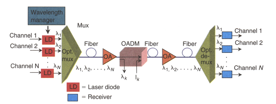
Point-to-point topology is typically found in long-haul transport, which demands for ultra high speed (10-40Gb/s), ultra high aggregate bandwidth, high signal integrity, great reliability, and fast path restoration capability. The transmitter and receiver within this DWDM topology can be several hundred kilometers away, and the number of amplifiers between the two end points is generally less than 10. Together with add-drop multiplexing, point-to-point DWDM topology enables the system to drop and add channels along its path. A DWDM point-to-point system includes lasers, an optical multiplexer and demultiplexer, fibers, optical amplifiers, and an optical add-drop multiplexer.
point-to-point dwdm topology
Ring-Configuration Mesh and Star Networks
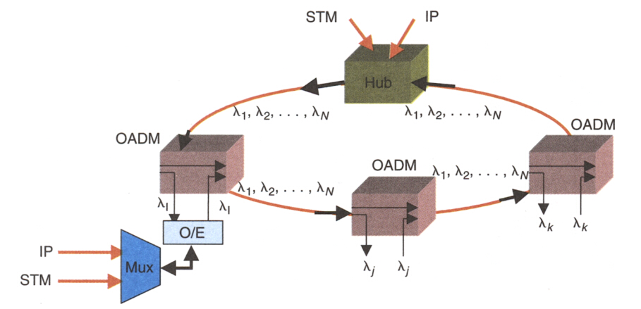
Basically, a DWDM ring network includes a fiber in a ring configuration that fully interconnects nodes. Two fiber rings are even presented in some systems for network protection. This ring DWDM topology is commonly adopted in a local or a metropolitan area which can span a few tens of kilometers. Many wavelength channels and nodes may be involved in DWDM ring system. One of the nodes in the ring is a hub station where all wavelengths are sourced, terminated, and managed, connectivity with other networks takes place at this hub station. Each node and the hub have optical add-drop multiplexers (OADM) to drop off and add one or more designated wavelength channels. As the number of OADMs increases, signal loss occurs and optical amplifier is needed here.
dwdm ring network
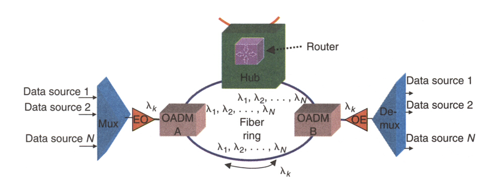
In the ring DWDM topology, a hub station works to manage channel assignment so that a fully connected network of nodes with OADM is accomplished. The hub also makes it possible to connect other networks. A DWDM mux/demux can be connected to an OADM node to multiplex several data sources. The following picture demonstrates a simple DWDM ring topology with a hub and two nodes (A and B).
dwdm ring topology with hub
Transmit and Receive Directions of DWDM Hub
In the previous part, we’ve mentioned DWDM hub, which serves as a very essential parts in a DWDM system. Here we further explain the transmit and receive direction of a DWDM hub, proving system solutions for your reference.
Transmit Direction
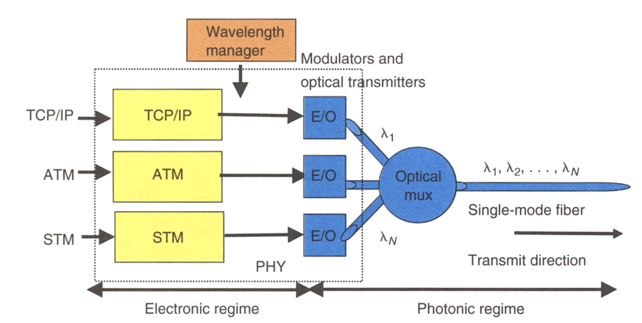
A DWDM hub accepts various electrical payloads, such as communications transport protoco/Internet Protocol (TCP/IP), asynchronous transfer mode (ATM), STM, and high-speed Ethernet (l Gb/s, 10 Gb/s). Each traffic type (channel) is sent to its corresponding physical interface, where a wavelength is assigned and is modulated at the electrical-to-optical converter. The optically modulated signals from each source are then optically multiplexed and launched into the fiber.
dwdm hub in the transmit direction
Receive Direction
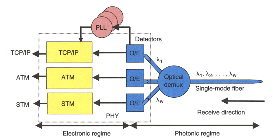
When a hub receives a WDM signal, it optically demultiplexes it to its component wavelengths (channels) and converts each optically modulated signal to a digital electrical signal. Each digital signal then is routed to its corresponding electrical interface: TCPIIP, ATM, STM, and so on However, that each channel requires its own clock recovery circuitry because all channels may be at different bit rates.
dwdm hub in the receive direction
Conclusion
The network topology of your DWDM system depends on various factors, including the number of nodes, maximum traffic capacity, scalability, number of fiber links between nodes and so on. Attentions also should be attached to the network components involved in the DWDM system. Hope this article could help to get more understanding towards DWDM technology.

Sunday, May 14, 2017

IP/WDM vs. IP/OTN: Which One to Choose?

The unceasingly demand for Internet-based services makes carrier IP networks a more critical social infrastructure. Operators are required to offer higher speeds, larger capacities and higher reliability network. There emerge two solutions to tackle this issue: IP/WDM and IP/OTN. IP/WDM consists of core routers connected directly over point-to-point WDM links, whereas IP/OTN connects the core routers through a reconfigurable optical backbone (OTN) consisting of electro-optical cross-connects (OXCs) interconnected in a mesh WDM network. This article guides you to choose between them.
Basics of WDM Technology
WDM technology is nothing new for us since it is rather prevalent especially for long haul data transmission. Its ability to provide potentially unlimited transmission capacity remains to be the most featured benefits. Either by simply upgrading the equipment or by increasing the number of lambdas on the fiber, network capacity can be obtained. It is the best choice for applications where channel density/bandwidth is of high priority. Aside from the bandwidth advantage, it also possesses these compelling merits.
wdm technology
  • Transparency—Being a physical layer architecture, WDM can transparently support both TDM and data formats such as ATM, Gigabit Ethernet, ESCON, and Fibre Channel with open interfaces over a common physical layer.
  • Scalability—WDM can leverage the abundance of dark fiber in many metropolitan area and enterprise networks to quickly meet demand for capacity on point-to-point links and on spans of existing SONET/SDH rings.
  • Dynamic provisioning—Fast, simple, and dynamic provisioning of network connections enable high-bandwidth services in days rather than months.
OTN Network Explanation
ITU-T defines OTN as a set of optical network elements (ONE) connected by optical fiber links, being able to provide functionality of transporting, multiplexing, switching, management, supervision and serviceability of optical channels carrying client signals. OTN was designed to optimize existing resources of a transport network. It is a digital wrapper that provides an efficient and globally accepted way to multiplex different services onto optical light paths. The advantages of OTN consist of the following aspects.
OTN network
  • It has the facility to work with DWDM and SDH equipment within banded or mesh networks.
  • Transmits SDH services, without termination of the signal at each network element, the signal transport is transparent including the clock and byte header.
  • Easily combine multiple networks and services on a common infrastructure entirely in the optical domain and transparent to the format and the speed of the signal carrying client, allowing you to create a multi-platform client.
  • The OTN services offering is gully software programmable via a single line card, so that the protocols, connectivity and functionality can be reprogrammed remotely as they change services or customers.
IP/WDM vs. IP/OTN: How to Choose From?
Before we go any further, let’s first look at the basic architecture of each. In the IP/WDM architecture, core routers are connected directly over point-to-point WDM links, whereas in the IP/OTN architecture, they are connected through a reconfigurable optical backbone (OTN) consisting of electro-optical cross-connects (OXCs) interconnected in a mesh WDM network. (See the figure below). We assume that each Point of Presence (PoP) or CO (Central Office) consists of four IP routers. It is clear that in IP/WDM, the routers are connected directly to the WDM systems, which connect them to neighboring PoPs. On the other hand, in IP/OTN, there is an intermediate element (OXC) which is responsible for connecting IP routers from different PoPs.
IP over WDM vs. IP over OTN
The major differences of these two approaches include the following aspects:
1. In IP/WDM, traditional transport functions such as switching, grooming, configuration and restoration are eliminated from the SONET/SDH layer and moved to the IP layer which is supposed to be enhanced by MPLS. Alternatively, the optical layer is the one that deals with the aforementioned, exploiting the intelligence of OXCs.
2. IP/OTN solution is more scalable than IP/WDM since the core of the network is based on the more scalable OXCs rather than IP routers.
3. IP/OTN is more flexible to traffic changes than IP/WDM.
4. IP/OTN, the optical transport layer provides the restoration services in a fast and scalable way (optical shared mesh restoration), whereas in IP/WDM restoration is achieved by IP rerouting which is a slow process and may lead to instability in the network.
5. When comparing the cost, IP/WDM appears to be a more cost-prohibitive solution than the IP/OTN architecture. Furthermore, as years go by and total traffic increases, the cost difference between both architectures is more severe.
Conclusion
From what we presented in the article, it is clear that IP/OTN is a more cost-efficient solution. And the savings increase rapidly with the number of nodes and traffic demands between them. Furthermore, IP/OTN is superior over IP/WDM in other qualitative terms like scalability, availability and resiliency. FS.COM endeavors to provide cost-effective and feasible optical network solutions. For more information, please visit www.fs.com.

Wednesday, May 3, 2017

CWDM Network: Technology Overview and Common Applications

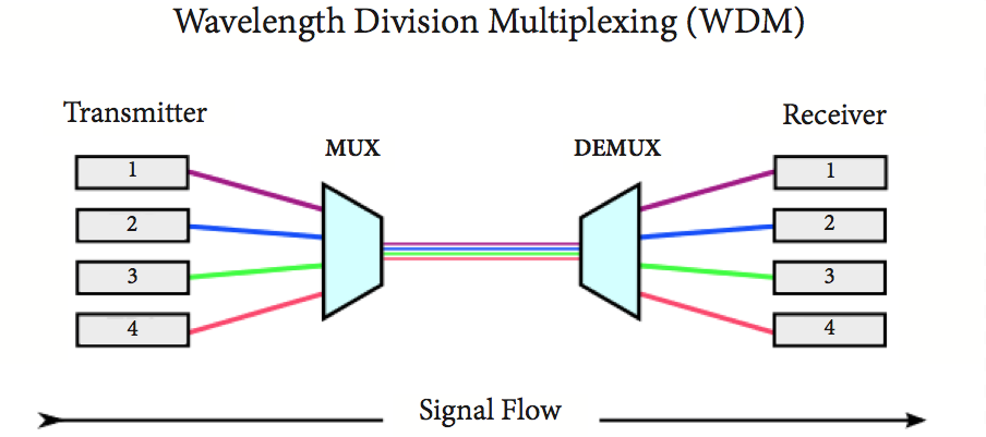
Fiber exhaust is an inevitable problem constantly faced by carriers since the demand for higher speed bandwidth never ceases. The ever-improving wavelength division multiplexing (WDM) technology nowadays is increasingly used to boost network capacity, enabling carriers to deliver more services over their existing fiber infrastructure. CWDM, as one form of the mature WDM technologies, is a perfect fit for access networks and metro/regional networks. This article addresses the CWDM fundamentals and its common applications, and how CWDM helps to maximize network capacity effectively.
CWDM Technology at a Glance
Coarse wavelength division multiplexing (CWDM) came into prominence as a cost-effective alternative to maximize network capacity in the access, metro and regional network segments. It gains in more popularity in area with a relatively moderate traffic growth due to its simple deployment and low cost. ITU-T G.694.2 defines 18 wavelengths for CWDM transport ranging from 1270 to 1610 nm, spaced at 20 nm apart. But 8 wavelength in the 1470-1610nm band is mostly used since there exist high attenuation in the 1270-1450 nm band. This technology shines out in access network deployments by obtaining the advantages of flexible add-drop capacity and network design simplicity.
CWDM wavelength
Common Applications of CWDM
After going through the basics of CWDM technology, this section will further explain its common applications. CWDM is primarily deployed in two areas: metropolitan and access networks. Let’s see how they could benefit from applying it.
Fiber Exhaust Relief
Fiber exhaust appears to be a severe problem that carriers endeavor to solve, especially for some metropolitan networks where data traffic increases continuously. Adding CWDM to the original optical network presents a cost-efficient and simple approach to this problem. In this case, carriers can add new services over a existing single optical fiber, while not interrupting service for existing customers. This solution is ideally suited for carriers that desires to increase the already installed network capacity without new fiber construction.
CWDM increases capacity
Enterprise LAN and SAN Connection
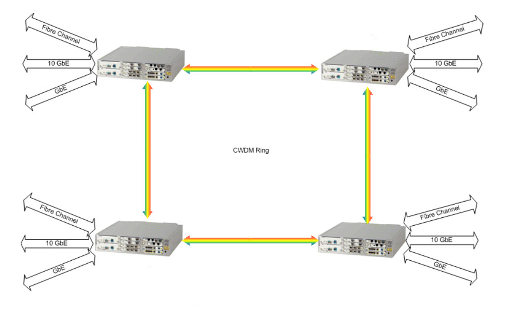
When interconnecting geographically dispersed Local Area Networks (LANs) and Storage Area Networks (SANs), CWDM rings and point-to-point links offer an optimum option. It is beneficial to integrate multiple Gigabit Ethernet, 10 Gigabit Ethernet and Fiber Channel links over a single fiber for CWDM point-to-point applications or for ring applications.
CWDM ring
Adoption in Metro Networks With Lower Cost
4 channel CWDM system offers an ideal solution for smaller metro/regional markets which demand for moderate traffic growth. This configuration can expand the available capacity four times over an existing network, enabling less deployment cost than the commonly adopted 8 channel system. Meanwhile, the scalability of this 4 channel system also allows carriers to upgrade to 8 channel systems when the need occurs.
Central Office to Customer Premise Interconnection
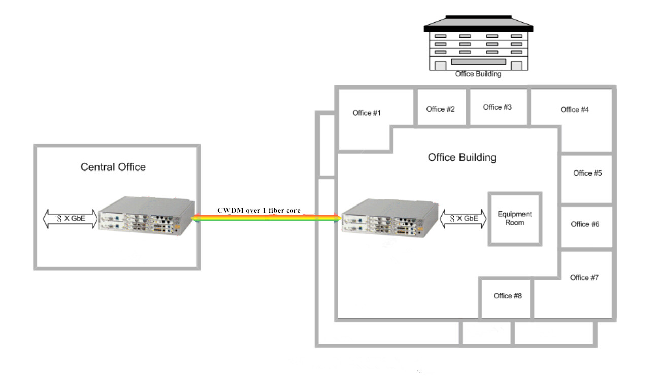
Coarse WDM system is also well-fitted for metro-access applications such as Fiber to the Building (FTTB). Let’s take the most widely used 8 channel CWDM network for example, it is capable of delivering 8 independent wavelength services from the Central Office (CO) to multiple business offices located in the same building.
CWDM for FTTH application
Combining With PON
Passive Optical Network (PON) is a point-to-multipoint optical network to deliver bandwidth to the last mile. It is cost-effective because it uses passive devices (splitters for example) instead of expensive active electronics. The issue exists in PON is that the amount of bandwidth they can support is rather limited. Since CWDM serves to multiple bandwidth, when combining it with PON, each additional lambda becomes a virtual point-to-point connection from a central office to an end user. If one end user in the original PON deployment needs his own fiber, adding CWDM to the PON fiber creates a virtual fiber for that user. Once the traffic is switched to the assigned lambda, the bandwidth taken from the PON is now available for other end users, so the access system can maximize fiber efficiency.
Conclusion
CWDM has clearly become the preferred method for increasing the bandwidth of metro/regional and optical access networks quickly, simply and at lowest cost. And it has proven to be sufficiently robust and reliable for upgrading the optical network to accommodate future growth. Hope this article could help to get a better understanding of coarse WDM technology.