Sunday, November 27, 2016

Understanding MTP/MPO Connectivity in High Density Data Centers

With the prevalence of cloud computing and big data, there comes a more demanding request for high-speed transmission and data capacity than ever since. In this case, 40/100G networks are more commonplace and now become a trend and hotspot for data-center cabling system. Meanwhile, most IT companies have realized that MTP/MPO cassettes, patch cords, connectors and adapters are essential backbone to their infrastructure. So, we will explain some basic factors in MTP/MPO connectivity in this article, with the purpose of better understanding this connectivity method.

MTP/MPO Connector Explanation

The need for transmission speed and data volume over short distances must be satisfied by choosing the right type of connectivity. So let’s start from the most basic yet critical part of MTP/MPO connectivity—MTP/MPO connector. It is known that 40/100G transmission utilizes parallel transmission, in which the data is simultaneously transmitted and received over multiple optical fibers (click here to know more about serial transmission and parallel transmission), thus a multi-fiber connector is required. MTP/MPO connectors which have either 12 fiber or 24 fiber array, will better support this solution.
MTP/MPO connector is the up-and-coming standard optical interface for 40G and 100G Ethernet network. The terms “MPO” and “MTP” are used interchangeably for this style of connector. MPO is the generic name for this Multi-Fiber Push On connector style. While MTP is a registered trademark and identifies a specific brand of the MPO-style connector.
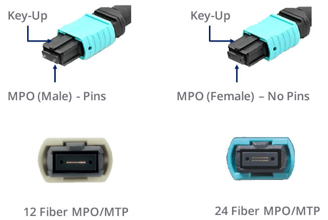
MTP MPO connector

MTP/MPO connectors are pin and socket connectors-requiring a male side and a female side. Cassettes and hydra cable assemblies are typically manufactured with a male (pinned) connector. Trunk cable assemblies typically support a female (unpinned) connector. The connectors are also keyed to ensure that proper end face orientation occurs during the mating process.
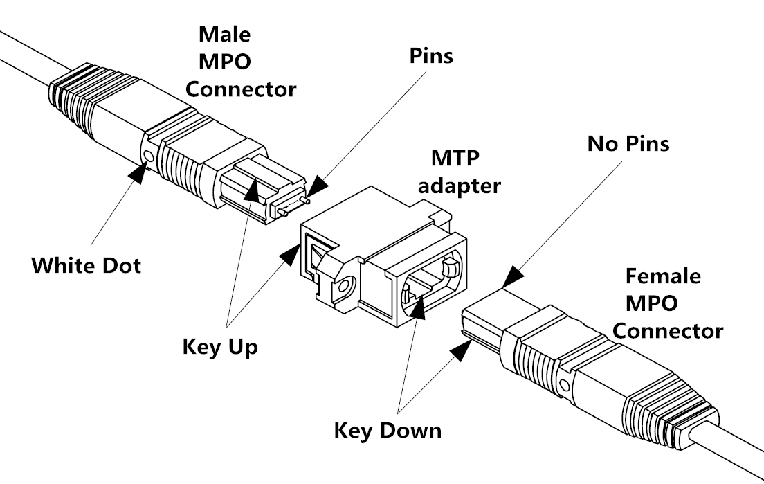
MTP MPO connectivity

Functions of MTP/MPO Connectivity in 40/100G Network

The widely used 10G system generally would utilize a single MTP/MPO (12 Fiber) connector between the 2 switches. Modules are placed on the end of the MPO connector to transition from a MPO connector to a 12 Fiber breakout LC duplex or SC duplex cable assembly. This enables connectivity to the switch. 40G and 100G systems require a slightly different configuration.
In 40G MPO connectivity system, an MPO connector (12 Fiber) is used. 10G is sent along each channel/fiber strand in a send and receive direction. This “lights up” 8 of the 12 fibers providing 40G parallel transmission.
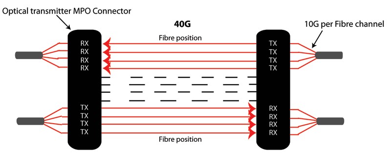
MTP MPO connectivity 40G

For optical 100G MPO connectivity system, an MPO connector (24 Fiber) is used (or alternatively 2 x 12F MPO Connector). 10G is sent along each channel/fiber strand in a send and receive direction. This “lights up” 20 of the 24 fibers providing 100G parallel transmission.
MTP MPO connectivity 100G

MTP/MPO Connectivity Components

Along with MTP/MPO connector, there are some other MPO components that used in high-density network interconnection. In essence, part of the MTP/MPO connectivity solution is a variety of fiber optic cabling components. Generally, there are two types of cables used in this solution:

One is a standard MTP trunk which has an MTP/MPO connector on either end of a 12 or 24 fiber ribbon cable. The connector construction can vary to the point where the 24 fibers are terminated into a single MTP/MPO connector, or they can be terminated into 2 separate 12 fiber MTP/MPO connectors.
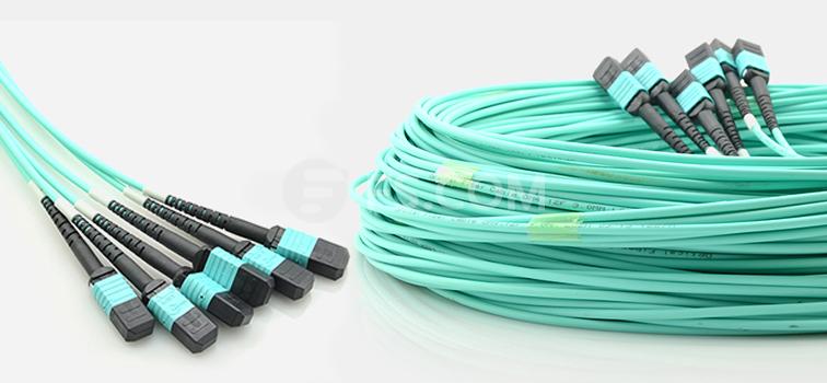
MTP MPO trunk cable

Another option used in this cabling configuration is a MTP/MPO breakout cable. This cable has an MTP/MPO connector on one end while the other end of the cable can have a variety of standard optical interfaces such as LC or SC connectors.
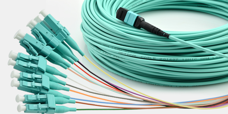
MTP MPO breakout cable

Moreover, these can connect directly into patch panels, MTP cassettes and active equipment. The MTP/MPO cassettes provide a central patching and fiber optic breakout point where the MTP interface can be changed to SC or LC type interface. MTP/MPO cassettes are typically housed in patch panel or fiber storage tray.
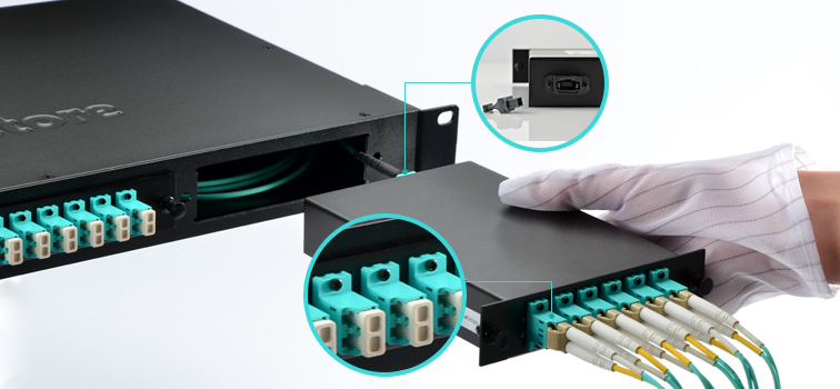
MTP MPO cassettes

Conclusion

In summary, MTP/MPO connectivity solution has proven to be an effective, feasible and flexible option to achieve 40/100G transmission, especially with the case of large- capacity and high-density data center environment. Not to mention that it also provides a reliable alternative for quickly connecting and rapid deployment. Hope the information offered in this article could at least help you understand this connectivity method. And for more information about MTP/MPO connectivity tutorial and products, please visit www.fs.com.
Considerations for Smooth 40/100G Migration with Fibers

We are now basking in a great boom in data transmission and information exchange, which results in an ever growing demand for higher speed and more reliable network. Currently, to migrate from legacy 10G to 40/100G network has become a hot topic yet irreversible trend. Part of this evolution, of course, was installing fiber optics in more network interconnection scenarios instead of copper cable. Among various connectivity methods, fiber optic cables have become the ubiquitous transport medium in the data center network. So, when employing fiber optic cable for 40/100G migration, some key considerations should be taken into account. That’s what we are about to explain in the following parts.

Selecting the Right Type of Fiber (Common Approaches Overview)

For data centers, the most cost effective fiber solution is a multimode fiber system. Surveys have shown that more than 80% of data centers are equal to or less than 100 meters. Moreover, multimode fiber transceivers are much less expensive than single-mode transceivers because they use a vertical cavity surface emitting laser (VCSEL) light source, which is easy to manufacture and package.

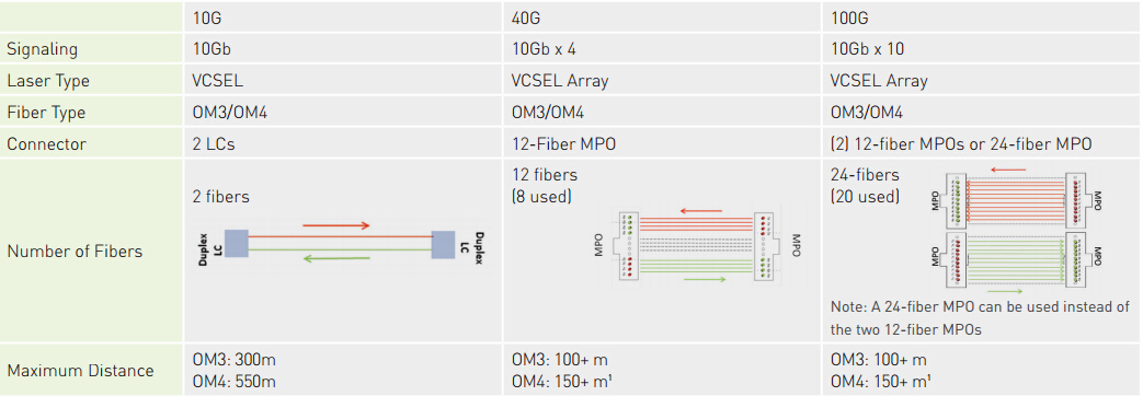
Although single-mode cable is less expensive, while concerning the total system cost of multimode versus single-mode, multimode becomes significantly less expensive. Thus selecting the right type of fiber will do you a good return in the long run. The following diagram presents some common approaches used in data centers. Each approach uses short-wavelength (850 nanometer) transmission over multimode fiber.
fibers-for-40/100G

According to the diagram, it is clear that the fiber system should be designed with OM3 or OM4 MMF to support 10G and beyond applications. OM3 supports 10G up to 300 meters, but only supports 40/100G up to 100m. OM4 supports 10G up to 550 meters, but only supports 40/100G up to 150 meters. If planning to support 40/100G in the future, the channel cannot be designed for the maximum distances that 10G can support. You should better design for the application that has the most stringent requirements (usually the fastest data rates) even if the application is a future installation.

Several Other Important Factors

Besides selecting the type of fiber, there are several other essential considerations to enable successful 40/100G migration. Which include channel insertion loss, polarity and alignment pins.

Channel Insertion Loss (Loss Budget)

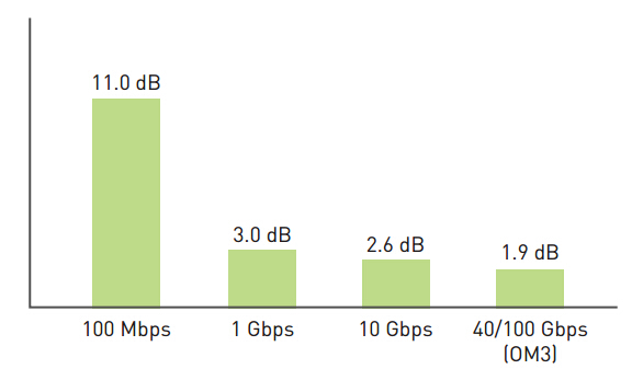
The channel insertion loss is made up of the insertion loss (IL) of the cable, the insertion loss of all mated connector pairs and the insertion loss of splices in that channel. And as the data rate increases from 10 Gbps to 40/100 Gbps, the total channel insertion loss decreases noticeably. The following picture shows total loss budgets for a 100-meter channel at different data rates common to current Ethernet applications. As data rates progress from 100 Mbps Ethernet-based systems to 10 Gbps Ethernet-based systems, the optical loss budgets have shrunk considerably from 11 dB to 2.6dB. 40/100 Gbps Ethernet systems have an even smaller budget of 1.9 dB when using OM3 or 1.5dB when using OM4.
channel insertion loss in 40/100G

Polarity

Proper polarity ensures an optical path from the transmit port of one device to the receive port of another device. There are several different methods to maintain polarity, but do remember that the different methods may not be interoperable.
Generally, there are three methods depicted in the TIA standards: Methods A, B and C (for more details click here). And each method requires a specific combination of components to maintain polarity. Here we take duplex signaling which uses an MPO backbone cable, cassettes and patch cords for example. The following shows the component options that are used in specific combinations for each of the polarity methods:
  • MPO-to-MPO backbone cables: Type A, B or C
  • MPO-to-LC cassettes: Method A or Method B
  • Patch cords: Type A-to-A or Type A-to-B
patch cords polarity

Polarity becomes more complicated when migrating to 40/100G because parallel transmission replaces duplex transmission. Parallel optical fiber links integrate multiple transmitters in one transmitter module, multiple fibers in fiber array connectors and multiple receivers in one receiver module. Multiple transmitters and receivers may also be integrated together in a transceiver module.

Alignment Pins

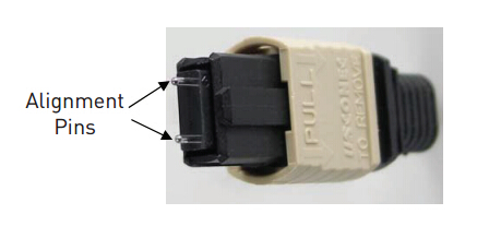
When mating connector plugs that use alignment pins, like the MPO connector, it is critical to ensure that one plug is pinned and the other plug is unpinned. Since general transceivers that accept MPO plugs are pinned, they accept only unpinned plugs. The picture below shows an MPO connector with pins installed.
MPO connector

The pinned connector is typically located inside the panel to help protect the pins from being damaged (i.e. the fixed connector is pinned and the connector that is frequently removed and handled is unpinned). For example, cassettes are typically pinned and trunk cables are typically unpinned. Do make sure the alignment pins are properly cleaned, or it could collect debris around the pins, which results in the two components not mating correctly.

Conclusion

To sum it up, for fiber installation in 40/100G migration, multimode fibers systems are more common and cost effective than single-mode systems for short distances. Select at least OM3, while OM4 will provide longer distance support or more connections over shorter distances. Channel insertion loss is the foundation, so consider high-performance, low loss components. Moreover, consider the polarity method to be used and for parallel transmission uses array connectors, decide which components require pins and which do not.

Monday, November 21, 2016

Advice on Pulling Fiber Optic Cable

According to many experienced cable installers, fail to pull cable properly will eventually lead to a series of network problems and disasters. Since installing cable is a routine yet fundamental task, its importance thus cannot be underestimated. Therefore, to ensure a smooth and efficient cable pulling process, installers should get fully prepared for the work, and take various factors into consideration to avoid damaging the cable. In this article, we try to explain how to prepare for pulling fiber optic cable and as well offer suggestions to help get the work done.

Before-Pulling Considerations

Preparation always serves as the very primary phase of the whole installation task. It can impact other stages in the process of pulling fiber optic cable. To get well-prepared, the following factors must be valued.
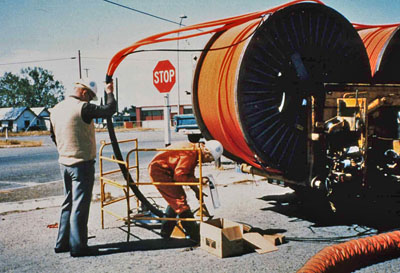
pulling fiber optic cable

1. Avoid Cable Damage

The first step in pulling  fiber optic cable is to measure and cut the material. Inaccurate measurements can result in disastrous issues. The glass fiber within the cable is fragile and requires greater care during the process of cable pulling. Damage to cable can come in many forms, and the common broken fiber is difficult to detect. The most common form of damage, a broken fiber, is also the most difficult to detect.

2. Despooling Cable Properly

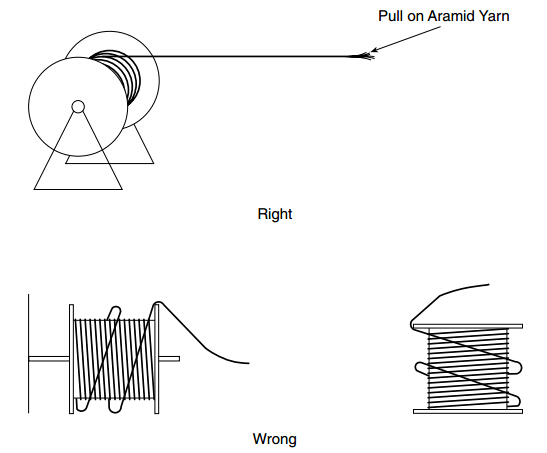
Improper pulling and despooling of the cable can cause optical cordage failure. One should also avoid cable twist when despooling fiber optic cable to prevent stressing the fibers. Therefore, cable should be reeled off the spool, not spun over the edge of the spool. This will eliminate cable twist, which will make coiling much easier.
despooling fiber

3. Pulling Force

The pulling force must be kept below a designated limit for the specific cable being installed. This is usually 600 pounds for outside plant (OSP) cable and 300 pounds or less for other cables. The pulling force must also be kept uniform. When using power equipment to pull OSP cable, tension monitoring equipment or breakaway swivels must always be used.

4. Bending Fiber Too Tightly

Another most common problem is bending the fiber on too tight a radius. A minimum bending radius of 10 cable diameters must be maintained over long-term, static conditions. When cable is placed under a tensile load while being pulled, a minimum of 20 cable diameters is recommended.

Which Jacket Type Is Right?

Indoor (Plenum): The cable is rated for all indoor installations, including plenum rated spaces. A cable rated for plenum installation will have low-smoke characteristics.

Outdoor: Outdoor cables are filled with a water blocking jell and are rated for all outdoor applications except for "direct bury". This cable is suitable for underground installation in conduit, overhead lashed to a guy wire, or secured to a building or other permanent outdoor structure. The only difference between outdoor (jell-filled) and direct bury cable is that the latter has an added overall metallic sheath which gives it protection from rodents.

Indoor/Outdoor: Indoor/Outdoor cables are approved for use in underground conduits, even if the possibility of water infiltration exists. Indoor/Outdoor cables are not recommended for aerial installations. This cable has an overall PVC sheath and is not rated for plenum spaces.

Procedures for Pulling Cable

Step One: Inspect the cable run to ensure there are no sharp bends or corners that exceed the minimum bend radius of the fiber.

Step Two: In many runs, if the pulling distance is short enough and the pathway straight enough, fiber-optic cable can be pulled by hand, without the use of special equipment. However, first make sure the pull does not exceed the tensile-loading limit established by the manufacturer for installation.

Step Three: When additional mechanical force is needed for a pull, use external pulling grips. This device locks onto and tightens around a cable as a tensile load is applied. The load is applied to the strength members of the cable rather than the optical fiber, itself.

Step Four: With some cables, such as outside-plant cable, it may be necessary to attach the pulling grip to strength members that surround the cable core as well as the outer jacket. This is done by sliding the grip past the end of the cable and then cutting the cable jacket back to expose the strength members.

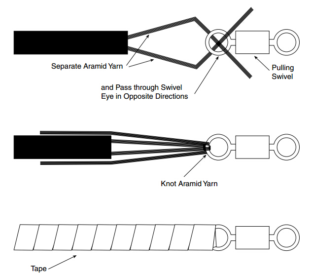
Step Five: Use a swivel when pulling fiber optic cable to make sure twists in the pull rope are not translated to the fiber-optic cable. Also, use a tension meter to monitor the tension being applied to the cable during the pull.
procedures of pulling fiber

Step Six: After pulling fiber optic cable, cut off approximately 10 feet of cable from the pulling end to remove any portion of the cable that may have been stretched or damaged during installation.

Note: Leave enough cable at either end to reach the work-area and closet terminating locations. You are now ready to terminate or connectorize the cable.

Conclusion
Pulling fiber optic cable is a dispensable and rather important part in fiber cable installation. During the process, installers should avoid cable damage, despoiling the fiber properly, and take pulling force into account. Since the real fiber pulling environment could be more complex, the recommended procedures we offered below simply provide guideline, and I hope it can be helpful.

Sunday, November 20, 2016

Speed Fiber Installation with Field Assembly Connector

The FTTH service nowadays has stretched its reach all around the world, and continues to expand. Naturally, optical fiber constructed to the home is expected to increase in various areas. Under such circumstance, a field assembly connector is commonly employed to streamline the installation process and simplify fiber storage. Thus field assembly connectors have found their position in the following occasions: inside closure, outside cabinet of home, inside ONU, and in premise cabinet. Then, how exactly installers can benefit from field assembly connector? This article will explain it in details.

What Is Field Assembly Connector?

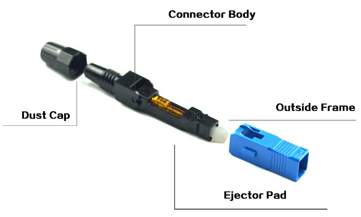
Field assembly connector, also known as fast/quick connector, is a pre-polished, field installable connector that designed for simple and fast field termination of single fibers. Eliminating the need for time-consuming polishing or adhesives. The heart of this fast connector is a pre-polished ferrule, and there exists a mechanical splice inside the connector body. Which enables a positive connection in the mechanical splice, thus achieving low insertion loss termination.
field assembly connector

Field assembly connector not only offers an immediate low loss termination to either single-mode or multimode fibers and are color-coded for ease of fiber identification, but also available for laser optimized 50μm (10G) fibers. It is compatible with 250 µm and 900 µm optical fibers, as well as 900 µm, 2mm and 3mm cordage.

Field Assembly Connector Structure

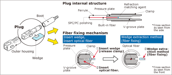
The following picture shows the internal structure of the field assembly connector. When connecting an optical fiber to it, the fiber is built into a ferrule (the end face of which is polished in a factory) of the connector. A factory-installed wedge clip holds the clamping mechanism open while the fiber is inserted. Once the fiber is in place, the wedge clip is removed and discarded.

Moreover, a mechanical splice is found at the end of the ferrule to enable the mechanical fixation of the fiber. This mechanical splice consists of plate A having V groove, plate B which is flat above V groove, and a clamp for the insertion of the two plates. Thus, the optical fiber has been positioned with high accuracy between V groove and plate B, held securely a place by spring power of the clamp.
field assembly connector structure

Benefits and Application

Then, here comes the question: how installers can benefit from the field assembly connector, and where it can be used?

Benefits:
  • Quick, simple and clean solution for terminating connectors.
  • Can be installed in within two minutes, including preparation time.
  • High success rate of connection.
  • Simple assembly process.
  • Factory polished reducing installation time.
  • Stable optical performance is achieved through its use of V-groove mechanical splice technology.
Application:
  • Premise/Enterprise Networks
  • LAN/WAN Connections
  • Patch Panels
  • Equipment Termination
  • FTTx Applications
  • Field Repair/Replacement
  • Equipment Test Leads

Assembly Manual

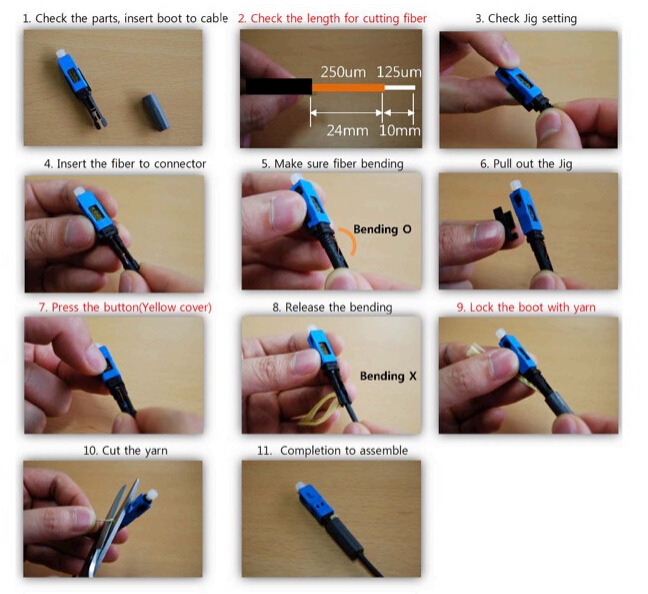
The field assembly connector can be assembled directly on the end of cable just within minutes. Which makes the installation process easy and fast. It requires no specialized tooling except standard fiber preparation tools: a fiber stripping tool, wipes and a fiber cleaver. Even no electrical power supply is needed to assemble this fiber connector. Here we provide a step by step guide to assembly the SC type fast connector for your reference. (see the picture below)
fast connector assembly manual

Conclusion

The factory-polished field assembly connector eliminates the need for any polishing materials, thereby enabling the preparation and termination of optical fiber in a fraction of the time. Meanwhile, it also allows for easy assembly and high performance of connectors. From the standpoint of good arrangement, time reduction, and quality management, field assembly connector is mainly used currently. Furthermore, the prevalence of which is also helpful for spreading the FTTH over the world.

Sunday, November 13, 2016

Tips for Successful Outside Plant (OSP) Installation

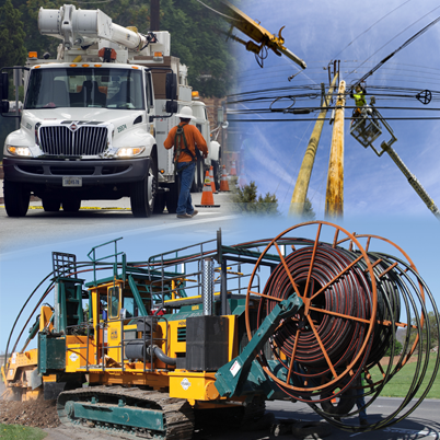
Outside plant installation (OSP), as the name indicates, is to install cable in outdoor applications, like placing cable underwater/underground, into buildings and at the top of poles. The process of OSP installation can be complicated and diverse owing to its complex conditions and environments. There are some important factors to consider before and when conducting OSP installation. And this is what we are going to talk about in this article: what exactly we could do to make the process seamless and flawless?

Prepare for OSP Installation

Well begun is half done. So the preparation work matters significantly. Let’s see what preparations are needed before installing OSP cables.
OSP

Hardware and Equipment

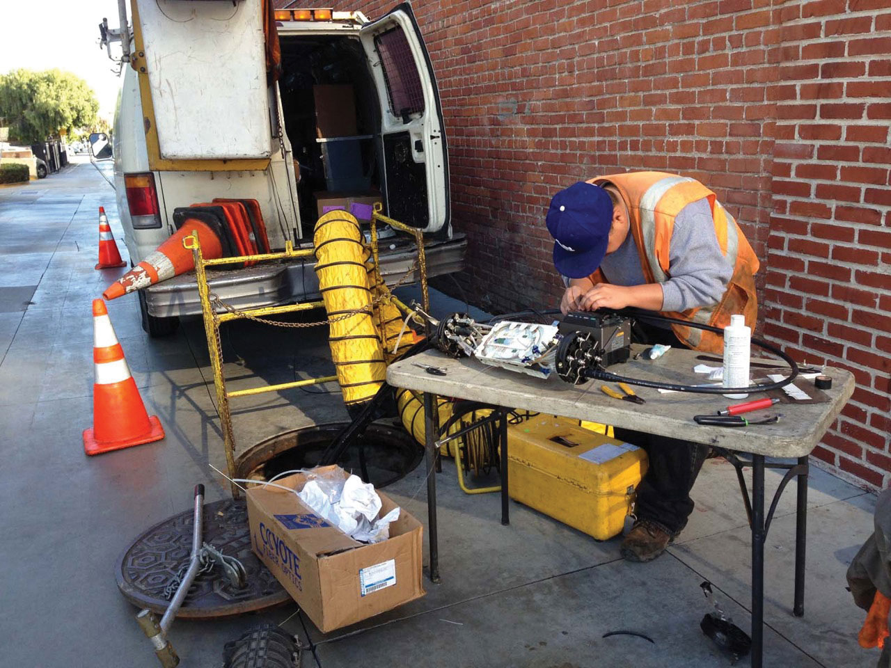
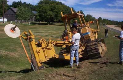
Before placing the cables, you may need to position those supporting structures, including new conduit, inner-duct manholes or sometimes even vaults. Then installers should consider all the hardware needed to be installed, as well as to schedule the specialized equipment required: trenchers or cable plows, backhoes, bucket trucks, cable winches, etc.
fiber splicing

Once the infrastructure is in place and the cabling pulled, fiber optic splicing work begins.Each splice must be verified with an optical time-domain reflectometer (OTDR) test. And do make sure to place each fiber properly in the splice closure and seal the closure carefully to protect it from degradation. Also, marking is necessary for easier fiber identification when problem arise.

Cable Termination

The OSP cables must be terminated or spliced to indoor cables soon after entering a building. Some OSP cables have double jackets, an outer one for outdoors and an inner one rated for indoor use. The outer jacket can be stripped off inside the building. Generally, single-mode OSP cables will be terminated by splicing pigtails onto each fiber, and splices will be placed in a splice closure. Multimode fibers can be handled the same way or terminated directly onto the fibers.
fiber termination

Safety

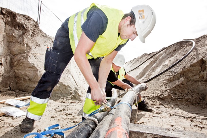
Safety is an important issue and always prior to all. Call before you dig to ensure no buried cables or pipes are in the proposed route. And Installers need to be well trained to operate the machinery safely. Every OSP job should have posted safety procedures and all personnel should be briefed in their use.

Considerations for Installing OSP Facility

Just as we stated at the beginning of the article. OSP installation is much more varied than those for premises. So, when installing OSP facility, besides making full preparation, you should also consider the following factors:

Choose the Right Cabling Media

Although the overall cable construction for outdoor installation can be various, the actual cabling media employed in OSP installation consisting of four basic types: single-mode optical fiber, 62.5/125- and 50/125-micron multimode optical fiber, unshielded twisted-pair (UTP) cable, and 75-ohm coaxial cable.

Optical fiber carries signals in the form of light pulses, which can be used for extended distances with greater bandwidth. Optical fiber is also lighter and more compact than copper wire (see the main differences) and is immune to electromagnetic interference (EMI) while offers greater security. As a result, fiber is well suited to heavy-industrial applications, where a great deal of electrical interference is common. It is also widely used in military installations for security reasons.

Copper cabling media transmit electrical signals. The twisted-pair cable (often in high pair counts) —is the mainstay of many regional and local telephone companies. However, twisted-pair is subject to electrical interference and has distance limitations when it comes to high-bandwidth applications.

Coaxial cable, or coax, is also a copper-based transmission medium, but it operates on a different principle. It is always the choice of cable-television providers and private broadband video networks. Coax offers higher bandwidth than twisted-pair, and it’s also less susceptible to interference. However, it’s more expensive, and it presents installation complications because its shielding must be grounded.

Deciding Installation Method

Three methods generally involved in installing OSP cables: aerial, direct-buried, and underground.

Aerial installations are the least expensive and are readily accessible for maintenance. Cables and other apparatus are mounted on utility poles in this method. However, they also pose several problems, including aesthetic concerns, susceptibility to environmental damage, and considerations of tension, sag, clearance, and wind- and ice-loading.
Aerial installations

Direct-buried installations are usually installed by means of trenching, plowing, or directional boring. They are less expensive than underground installations. But they are less flexible than conduit once installed, because they cannot be upgraded or expanded. Moreover, they may be difficult to relocate for repair, and they provide less physical protection for transmission media than conduit.
Direct-buried installations

Underground installations pull cable through conduit, thus offer the aesthetic appeal as well as provide greater cable protection, and offer more potential for future upgrades. However, this method is more costly than direct burial and requires more careful route planning.
underground-installation

Conclusion

To sum it up, to ensure the OSP installation process is smooth and efficient, get fully prepared is a fundamental yet essential part. Moreover, choose the right cabling media and installation method also counts for the whole process. Your choice should base on your specific situation and OSP environment. Hope what we presented in the article is informative enough.

Friday, November 11, 2016

How to Use Punch Down Tool?

Network performance and reliability are the foundation of a robust and sound communication system. Therefore, to ensure a successful connection between the computers and the data center, network technicians need the right assistance tools, punch down tool among which, is extremely essential for the smooth networks running. So, in this article we will offer you some tips on how to use punch down tools effectively.

Punch Down Tool Description

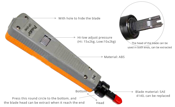
Also referred to as krone tool, the punch down tool is a small hand tool most often used by telecom and data network technicians to install wiring for telephone, computer and various audio networks. This tool allows for the quick and effective cross-connection of wires through the use of 66-type or 110-type connection blocks.
punch down tool

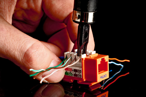
Punch down tool is commonly used for the termination works in the copper network. It is used to terminate the Ethernet cables (Cat5/5e/6/6a) by inserting the cables wires into the insulation-displacement connectors (IDC) on the punch down blocks, patch panels, keystone modules, and surface mount of boxes. The name is thus derived from the method by which the tool pushes a solid copper wire between metal blades on the connection block, and cuts off the excess by punching the tool, driving the tool blade through the wire.
punch-down-process

Guide to Using a Punch Down Tool

When there comes the need to repair or install cables, you’ll inevitably need to cut and secure wires. However, exposed wired can be dangerous and may cause your connections to short out. Punch down tool thus is necessary to ensure that your wires are secure, and meanwhile to help trim and contain the wires in a basic jack. Then how to use the punch down tool? Here we offer you a guide for reference.

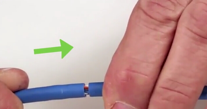
Step One: Strip back the cable jacket

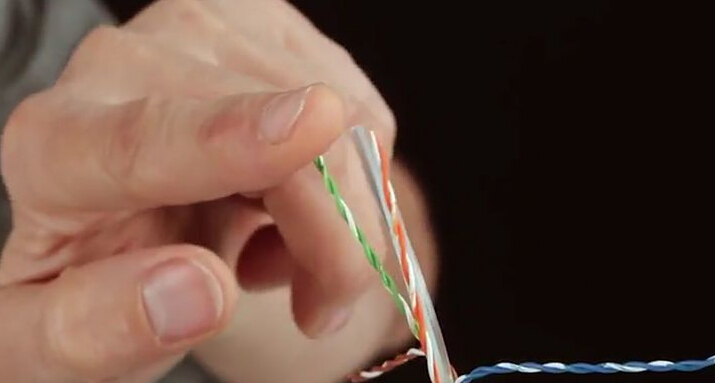
What should be noticed is that always leave about 2.5 inches (6 cm) at the end of the cable. Insert the cable into the cable stripping tool or modular crimping tool, and spin it around a few times. Then remove the jacket. Stripping back the cable will help you remove the jacket to expose enough of the cable, so you can separate it.
Step 1

Step Two: Expose the wires

After removing the cable jacket, you will have a few inches of exposed cable. Then gently pull away the wire pairs from the center of the cable so they fan out. Separate the wire pairs by twisting in a counterclockwise motion. Try to straighten the ends as much as you can, and this can make them easier to terminate.
Step 2

Step Three: Place the cable wires in the jack

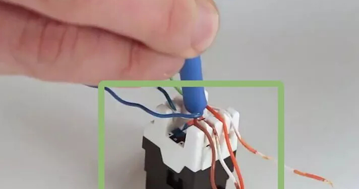
Take the protective cover off the top of the jack and set the cable into the block of the jack. Insert each wire into its own separate slot, making sure that the wire matches the A or B configuration. The conductor wires should be extending out of the jack.

Note: Consider to choose between T568A or T568B wiring scheme. The T568B is becoming more popular since it can be used with older color codes as well as newer codes.
Step 3

Step Four: Terminate the conductor wires

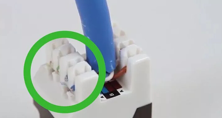
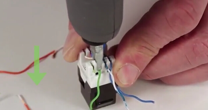
Take your punch down tool and press it down on the conductor wires to cut them. The angled (cut) part of the blade should contact with the long sturdy side of the jack. This will also make sure the wires that are cut are flush with the jack.

Note
  • Be sure to punch straight down and not at an angle. This will prevent the jack from bending.
  • A loud click along with the punch down action means that you've terminated the wire correctly.
Step 4

Step Five: Inspect the wires

Look at each wire to make sure there is no overhang out the side of the jack. You should also make sure that the edge of the cable jacket is near the base of the jack and the wires you just terminated. The wires should be securely in place. If you notice wires sticking out the side, take a wire cutter and carefully trim the wire so that it's flush with the jack.
Step 5

Step Six: Place a dust cap on the jack.

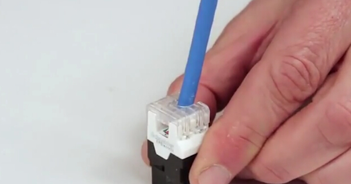
Snap the dust caps in place to protect the wires. This will keep the connection secure and can prevent strain on the wires. The dust cap is also very easy to remove: simply pop off the dust cap using a flat-head screwdriver inserted into the indentation on the side.

Note: Fail to set the dust caps back on the jack indicates that your wires may not be seated correctly. It is better to check the wires again and make sure they are secure and trimmed.
Step 6

Conclusion

Punch down tool is an easy-to-use and convenient network instruments that helps ease the difficulty of termination job. It also efficiently contributes to reduce termination time. FS.COM offers a wide range of punch down tools of top notch quality and with reasonable price. For more information, visit www.fs.com.
Friday, November 4, 2016

Why You Should Value Structured Cabling?

Nowadays, all businesses need to focus on the IT basics more than ever, be it small startups or middle and large-sized enterprises. Companies rely heavily on a good communication system to distribute their vital business information globally. Therefore, businesses are always looking for the best solutions for their telecommunications systems, which need to be effective, yet low-maintenance. In this case, structured cabling systems come in as a feasible and efficient solution, and their benefits cannot be underestimated.

What Is Structured Cabling?

Structured cabling forms the basis of the telecommunication system of modern business. It offers a general environment for data transmission by integrating telephone networks, video surveillance, security, local computer and other systems together. A structural cabling system supports multiple voices, data and multimedia systems. It basically means crafting a cabling infrastructure that comprises of sockets, cables and cable distributors.
structured cabling

To make it simple, structured cabling is the infrastructure that supports any LAN (local area network). Your LAN supports all of your telecommunications – phone, email, file sharing, data transfers, video surveillance and anything else that requires the transfer of information. Together, they enable you to connect to wider networks. It helps businesses or enterprises to improve the workflow and downtime issues.

How to Build Structured Cabling System

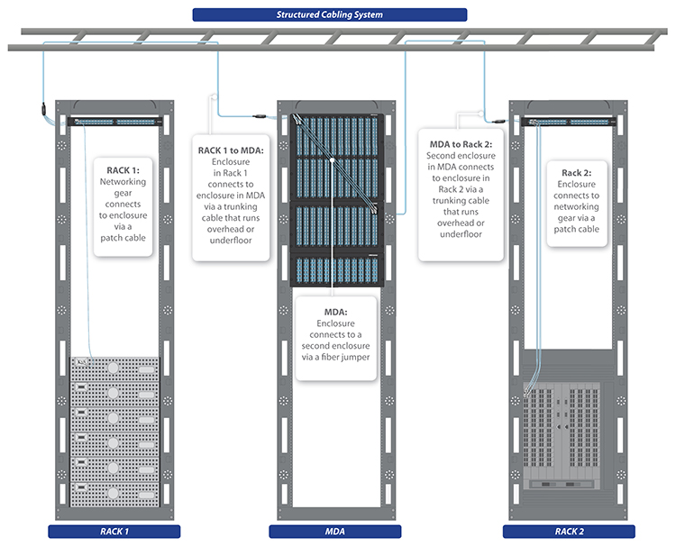
In a structured cabling system, patch panels and trunks are used to create a structure that allows for hardware ports to be connected to a patch panel at the top of the rack. That patch panel is then connected to another patch panel via a trunk (multi-fiber assembly designed for use in conveyance) in the MDA (main distribution area). The MDA is the key aspect of structured cabling. This is where all the MAC’s (moves, adds, and changes) can be made with short length patch cords.
structured cabling system

A properly designed and installed structured cabling system, therefore, provides a cabling infrastructure that delivers predictable performance. It has the flexibility to accommodate moves, adds and changes to maximize system availability. Besides, it is also able to future-proof the usability of the cabling system.
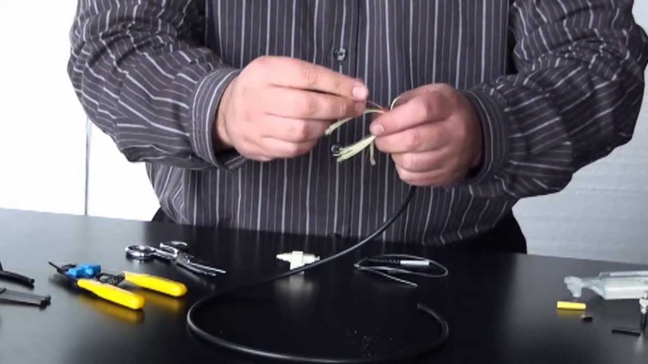
However, there exists several risks if NOT switching to a structured cabling system:

Mistakes are commonly made with an unorganized messy cabling infrastructure. Like incorrect ports are unplugged. Even worse is the messy cabling that gets in the way. Trying to remove a single cable from a large tangled mess can inevitably cause stress on the other cables. This stress can lead to network errors in the hardware that are very difficult to trace.
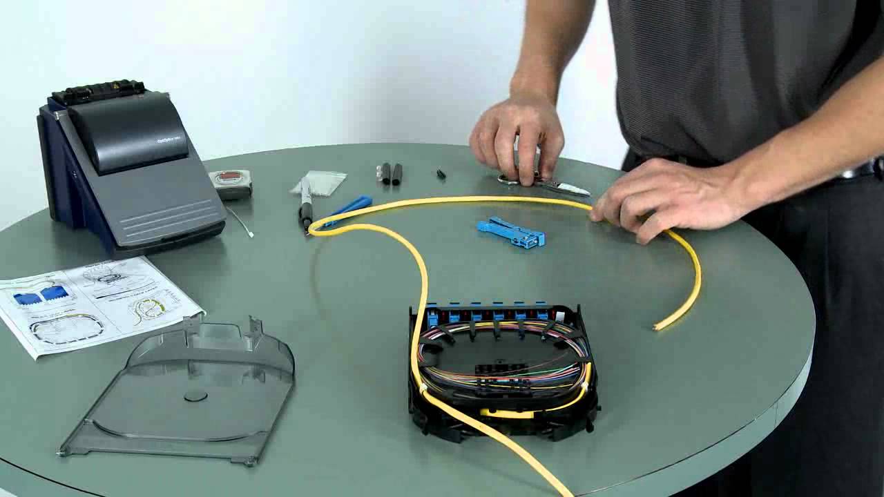
Another risk lies in the airflow. If a point to point method is used, the front and potentially the sides of the switch are congested with cabling bulk. This impedes the airflow that the switch needs to operate. This also translates to underfloor cooling, cabling congestion in this space hinders the airflow of the CRAC unit and can cause cooling issues.

Benefits of Structured Cabling System

Basically, structured cabling system consists of the following five advantages.

Simpler to Manage

You only need minimum staff to administer and manage your data center cabling. And changes of the system can be done in a faster, more efficient way, with minimal disruption.

Higher Return on Investment

Data, voice and video are unified in a structured cabling system. That unified structure reduces the need for updates thus lowers your maintenance costs. Besides, any adds, moves or changes can be made within the system with ease, which saves your company both time and money.

Better Prepared for Expansion

High bandwidth often comes with structured cabling. That means it will be able to support future applications you may add, with little interruption to your current system. As a result, you can rest assured knowing your system won’t become dated after just a few years. Instead, your system’s vast infrastructure will adapt with your telecommunication needs.

More Flexibility Within Your System

Multiple wiring systems can be troublesome. A structured cabling system, however, consolidates your wiring system into a single infrastructure that transfers data in multiple formats. And it allows for efficient changes and upgrades. This flexibility also makes it easier for the system to move to a new location if needed.

More Aesthetically Pleasing

For each and every data centers, aesthetics matter, too. Structured cabling enables a cleaner, less cluttered look than a point-to-point cabling system. Meanwhile, this system is more efficient and easy to use. And the reduced congestion decreases the chances for blocked airflow and crushed cables.
structured-cabling

Conclusion

Your cabling is the backbone of your IT network, a complex system of routers, switches, and servers. A structured cabling system efficiently meets all your communications needs, and streamlining your entire IT network in a way that the traditional point-to-point system simply cannot do. If you want a simplified system that maximizes functionality and saves your business both time and money, structured cabling is the way forward.

Thursday, November 3, 2016

Suggestions on Selecting Cabling Component

Cabling component selection actually serves as the very primary stage of installing the system, and it can pose continuous impact on the reliability and flexibility of the whole network. It is sometimes overwhelming for installers to narrow down and select the right combination of cabling components since there are quite amount of them available on the market. Deploying the right equipment can avoid future cabling issues. So, before making the decision, you’ d better consider compatibility, ease of installation, cost, density, durability, aesthetics, accessibility, flexibility, and delivery times. Here, we offer you some advice on how to choose the right cabling component.

Patch Cables

Patch cables are used to connect end devices to patch panel ports, and to connect ports between two patch panels. A big problem concerning patch cables is the design and quality of the terminations, especially for RJ45 copper terminations. The quality of patch cables matters a lot since they will experience the most wear and tear. Hence when purchasing patch cable, please take the following aspects into account:
  • Specification of the cable, avoid cheap, low-quality cables
  • Compliance to EIA/TIA/IEEE standards
  • Thickness of the copper cable, the thicker the better
  • Flexibility of the cable, the less cable memory the better
  • Connector design and quality
  • Availability of colors and categories, prepared for current and future needs
  • Support for future applications

Patch Panels

Patch panel enables easy management of patch cables and links the cabling distribution areas. Multimedia patch panels are ideal since they allow several different cable connectors to be used in the same patch panel. As for the types of connectors, consider LC for fiber and RJ-45 for copper. While mixing cable types within the same patch panel is not best practice, it is more flexible for housing ad-hoc cable types. The best solution is to separate the fiber cabling from the copper cabling in separate patch panels. Patch panels also come in modular styles, for example, for an MPO structured system, which features faster installation and lower labor cost. And there are angled patch panels for high-density areas cabling. Consider the following when selecting patch panels.
patch panel cabling
  • Spacing between ports aids insertion and removal of cables
  • Sturdy connectors: some panels have loose connectors and tend to fall out during cable installation and removal
  • Orientation of ports in the panel
  • One-piece dust covers for ports (recommended for high traffic areas)
  • Density supported (24 ports or 48 ports per 1U panel)
  • Compatibility with industry standard connectors and racks, and space for labeling on the front of the panel
  • Added cable support for the intended cable types on the back of the panel, this is critical and overlooked by many manufacturers.

Horizontal and Backbone Cables

Choose the fire-rated plenum type. There are no high-density copper solutions, but you can choose a modular cabling system. As for fiber, high density involving 24-strand to 96-strand cables in adequate. MPO trunk cables (up to 72 fiber strands can be housed in one MPO connection) can be installed if you are using MPO style cabling. It is necessary to evaluate the cost of materials and labor for terminating connections into patch panels. These cables will most likely end up under raised floors, or over the ceiling, or in overhead cable pathways.

Cable Managers

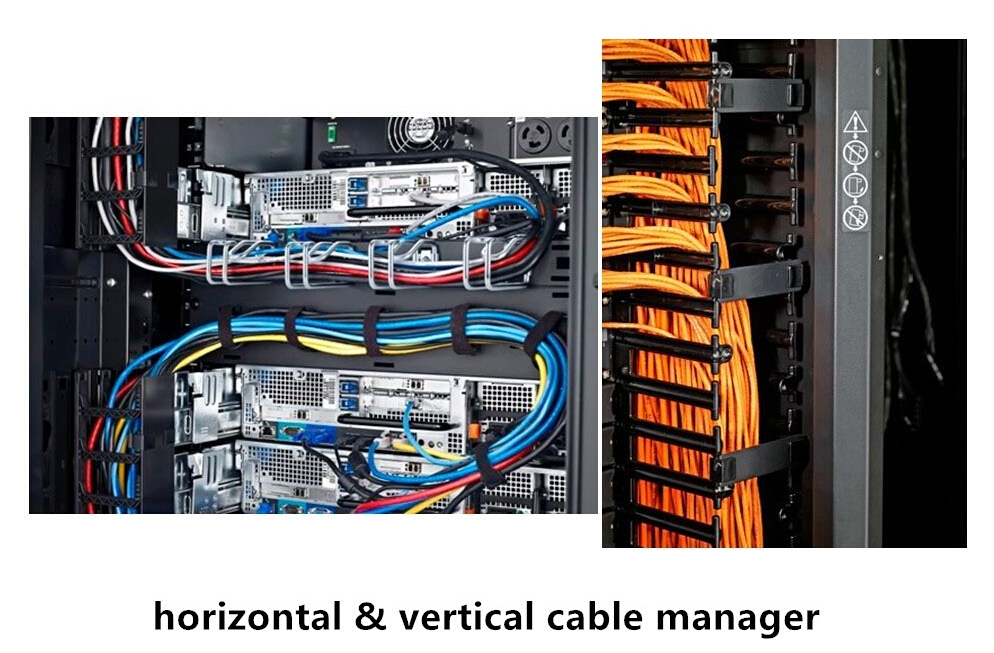
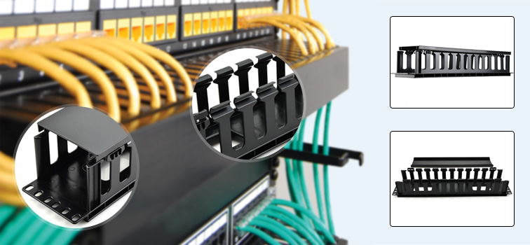
There are horizontal and vertical cable managers for different cabling methods. Horizontal cable managers contribute to proper and neat routing of the patch cables from equipment in racks and protect cables from damage. It is vital to reach a balance between cable manager height and cable density supported. 1U and 2U horizontal cable managers are the most common ones, with metal and flexible plastic available. The ideal cable manager has a big enough lip for positioning and removing cables easily, and has sufficient depth to accommodate the quantity of cables planned for the area. Remember that 30% space in the cable managers should be left for future growth.
cable managers

As for vertical cable managers, additional space is required to manage the slack from patch cords. And you should ensure that the managers can easily route the largest cable diameter in your plan. Allow for 50% growth of cables when planning the width and depth of the vertical cable manager. For dynamic environments, d-rings type cable managers are used to manage cables on the back side of the racks. Whereas for static environments, consider installing another vertical cable manager behind the rack, which allows for access to components in the space between the racks.

Overhead Cable Pathways

Known as overhead cable trays as well, they allow placement of additional cables for interconnecting devices between racks on an ad-hoc basis. Check support for cable bend radius, weight allowance, sagging points for cables, and flexibility in installing the pathways. Besides, ensure that pathways allow cable drop points where needed.
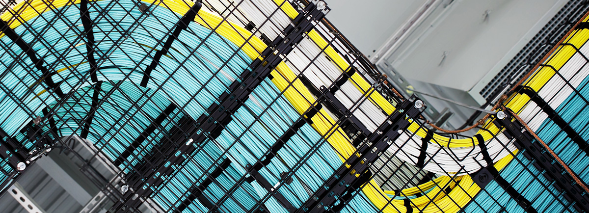
overhead cabling

Cable Ties

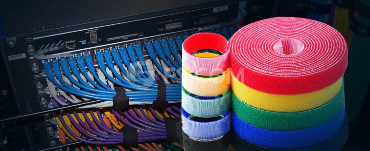
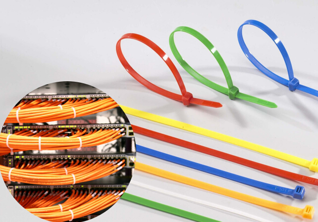
Cable ties are used to hold a group of cables together or to fasten cables to other components. Since there is a tendency for users to over-tight zip ties, which definitely can impact performance, it is advised to choose velcro cable ties versus zip ties. Velcro cable ties are available in a roll or in pre-determined lengths. Using cable ties to bundle groups of relevant cables together will help you better identify cables and facilitate overall cable management.
cable tie

Conclusion

It is clear that selecting the right cabling components to best satisfy your specific cabling structure can be time and energy consuming, with the components range from patch cables to ports to panels and to cable managers. The article simply provides you a reference guideline to compare and select. And we hope it could release you from the laborious and demanding selection task.

How to Achieve Cable Management in Rack System?

Currently, most data centers and server rooms feature high density and large capacity, in which the devices and switches are installed on rack to achieve better performance and scalability. The accelerating capacity of network, therefore, brings a parallel growth of discrete data communication and power cabling. Apparently, to manage these massive data and cables within a confined and tightly-spaced rack environment is quite difficult. Improper cable management would result in cable damage and failure, which directly lead to data transmission errors, performance issues and system downtime. So, in this article, let’s talk about cable management in rack cabling systems.

Why Proper Cable Management Is Important?

Just as we have mentioned previously, poor cable management can cause a series of network problems. The following are the common ones.

Signal interference and crosstalk due to improper placement of data and power cables—Data and power cables running close to each other in parallel groups or in loops may create electromagnetic interference (EMI) due to induction. EMI can cause errors in data transmission over these cables. Therefore, power cables should be necessarily separated from data cables on the opposite side of the rack to reduce the chances of EMI.

Rack-mounted components blocked by improperly routed cables—Having the access to servers and other network components housed within an enclosure is critical. Due to the high density cabling of these applications, it is important to ensure that cabling does not block components, racks or rails. Fiber optic cables encounter additional challenges since they are more fragile. One should prevent other cables or components from exerting tension on fiber cables and avoid damage. Cable ties can be used to secure fiber optic cables. Try not to route fiber optic cable around corners within the enclosure.
nylon-cable-tie

Cooling and airflow restriction resulting from poor cable placement—It is important to make sure that cables are not placed in such a way that may restrict airflow from components inside the enclosure. Obstructed air movement due to blocked vents and fans lead to component overheating and possible thermal shutdown or even equipment damage.

Cable Management in Server Cabinets

At the very beginning, we should know that data centers generally contain two basic types of equipment enclosures: server cabinets and network cabinets.
Server cabinets house mostly active equipment in the form of blade chassis or stackable servers. The first step of preparing cable management for the enclosure is to determine the capacity needed for cabling. Calculate the number and type of connections per server and the total number of servers expected to be housed in the cabinet, then to determine where the cable needs to be routed.

Cabling Requirements Unique to Server Cabinets

Server cabinets typically have the patching for the devices occupying the rear-facing portion of the cabinet, along with power connections. This requires management of both network and power cords. The copper connections and fiber connections are served from one vertical bay, while power connections are addressed from another bay.
A mounting area is provided where vertical mounted power strips are used. In instances where power and network cords have to cross from one side of the cabinet to the other, the use of horizontal cable managers can be deployed to provide distinct paths. Noted that power and network cords should be housed in separate cable managers. The ability to house these connections in the vertical patching space assures that cables are dressed in such a manner that they do not block exhaust fans on the rear of the servers.
cable-management-panel/rack

Cable Management in Network Cabinets

Network cabinets house network switches and patch panels. These cabinets have the highest concentration of cabling in the data center, making patch cord management even more critical and requiring both horizontal and vertical cable management. Due to the high concentration of cabling in these cabinets, a typical installation would use 19’’ patch panels and standard fiber enclosures mounted either at the top of the switch cabinet or in an adjacent cabinet when the cabinet houses multiple switches.

Cabling Requirements Unique to Network Cabinets

The majority of the patching connections typically occur at the front of the cabinet. For in row switching or top of rack switching, the back side rails populated with a horizontal cable managers allow patching within the cabinet and down the row.
Typically, the cabinets would be configured in a manner using rack mount patch panels and cable managers along with vertically mounted cable managers to provide pathways for patch cords transcending from top of rack patch panels to bottom of rack switches.

Tips for Specifying and Applying Cable Management Products

Start with proper planning—Once you have determined the amount of cabling and connections required, you can decide where the cables need to be routed within the cabinet. This allows you to select the proper cable management components to secure the wiring and connections. It is important to make sure that there is adequate space within the rack for the amount of cabling. Accurately establishing the amount of cabling and connections needed ahead of deployment will greatly increase the chance of a successful installation.

Keep growth in mind—Growth in data center environment is a necessity. Planning ahead for installing additional cabinets, servers and network components should be taken into consideration even as you are in the first phase of your rack installation. Which makes it easier to integrate additional racks and components in the future. Poor planning in terms of future changes often results in cable spaghetti that presented in many data centers.

Follow industry standards—Industry guidelines such as ANSI/TIA and ISO/IEC, as well as any federal, state or local regulations regarding cabling should always be followed. It not only assures code compliance but promises a safe, failure-free installation that will minimize system downtime and data errors. A standards-based cabling system provides the best combination of reliability today and the ability to change and reconfigure in the future. Standards provide a written foundation for establishing a sound infrastructure and guidelines for maintaining a high level of cable performance.

Summary

As we can see, poor cable management could lead to additional cost and time, while proper management contributes to reduce signal interference, improve maintenance and serviceability. To achieve successful cable management, professional skills and experiences are needed. And with the help of management products like cable manager and cable tie, you can even manage cables more efficiently according to specific layout requirements.

Originally published: http://www.china-cable-suppliers.com/achieve-cable-manage-rack-systems.html

Tuesday, November 1, 2016

How to Choose a Perfect OTDR?

The past few years have witnessed the boom in optical fiber being used in network communication industry. In order to make sure that the fiber network is reliable and accessible, a more accurate and faster methodology for assessing the integrity of the infrastructure is indispensable. Therefore, it is essential to choose the right fiber optic testing tool/device: not only to meet the enhanced testing requirements, but also help to increase the reliability and value of the whole network. OTDR is one of the most powerful test instruments for fiber cable testing.

What Is OTDR?

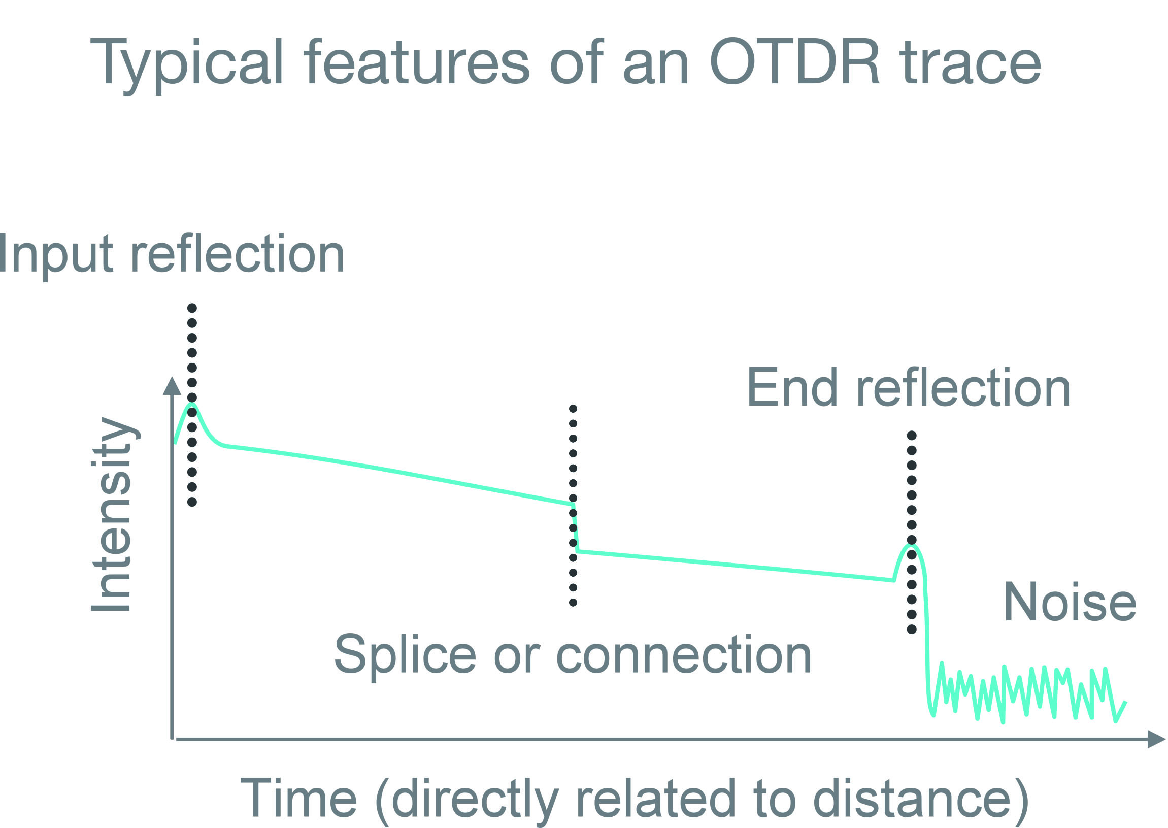
OTDR (optical time-domain reflectometer) is used to test the performance of newly installed fiber links and detect problems that may exist in fiber links. The purpose of it is to detect, locate, and measure elements at any location on a fiber optic link. An OTDR needs access to only one end of the link and acts like an one-dimensional radar system. By providing pictorial trace signatures of the fibers under test, it’s possible to get a graphical representation of the entire fiber optic link.
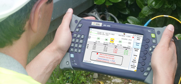
OTDR

Just by injecting pulsed of light into one end of a fiber and analyzing the back scattered and reflected signals, an OTDR can thus measure:

Optical Distance
  • To elements: splices, connectors, splitters, multiplexers
  • To faults
  • To end of fiber
Loss, Optical Return Loss (ORL)/Reflectance
  • Loss of splices and connectors
  • ORL of link or section
  • Reflectance of connectors
  • Total fiber attenuation
OTDR trace

Why Need an OTDR?

Fiber testing plays a significant role in ensuring the network is optimized to deliver reliable and robust services without fault.

For Outside Plants (OSP)

Service providers and network operators want to insure that their investments into fiber networks are protected. In outside fiber plant, every cable will be tested for end-to-end loss and with an OTDR to ensure the installation was properly made. Installers will be asked to use loss test sets (source and power meters) as well as OTDRs, performing bi-directional tests and providing accurate cable documentation to certify their work. Later, OTDRs can be used for troubleshooting problems such as break locations due to dig-ups.
OSP OTDR testing

For Premises, LAN/WAN, Data Centers, Enterprise

Premises fiber networks have tight loss budgets and less room for error. Installers should test the overall loss budget with a light source and power meter. OTDR testing is a best practice that can pinpoint the causes for excess loss and verify that splices and connections are within appropriate tolerances. It is also the only way to know the exact location of a fault or a break. Testing a fiber link with an OTDR also helps document the system for future verification.

Factors to Consider When Choosing the OTDR

For different test and measurement needs, there exist a great number of OTDR models, then how to select the right one? A comprehensive understanding of OTDR specifications and the application will help make the choice. Moreover, based on your specific need, you should answer the following questions before looking for an OTDR:
  • What kind of networks will you be testing?
  • What fiber type will you be testing? Multimode or single-mode?
  • What is the maximum distance you might have to test?
  • What kind of measurements will you perform? Construction, troubleshooting or in-service?
And when choosing an OTDR, you should take these factors into consideration:
  • Size and Weight—important if you have to climb up a cell tower or work inside a building
  • Display Size—5” should be the minimum requirement for a display size; OTDRs with smaller displays cost less but make OTDR trace analysis more difficult
  • Battery Life—an OTDR should be usable for a day in the field; 8 hours should be the minimum
  • Trace or Results Storage—128 MB should be the minimum internal memory with options for external storage such as external USB memory sticks
  • Bluetooth and/or WiFi Wireless Technology—wireless connectivity enables easily exporting test results to PCs/laptops/tablets
  • Modularity/Upgradability—a modular/upgradable platform will more easily match the evolution of your test needs; this may be costlier at the time of purchase but is less expensive in the long term
  • Post-Processing Software Availability—although it is possible to edit and document your fibers from the test instrument, it is much easier and more convenient to analyze and document test results using post-processing software
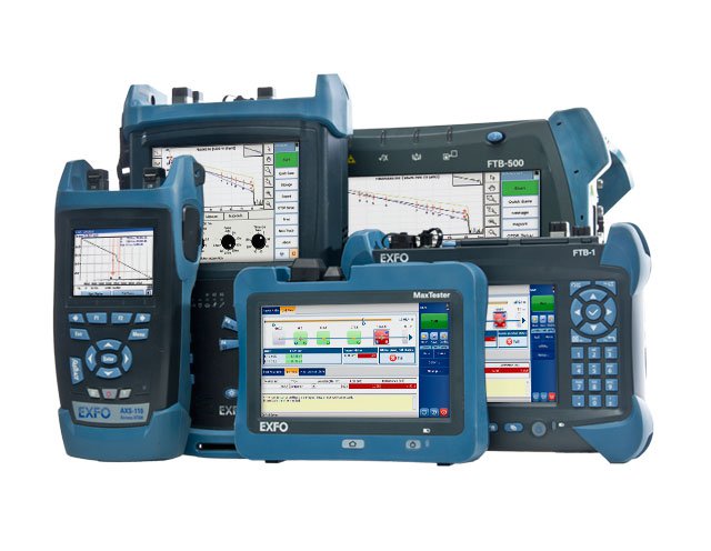
OTDR

Conclusion

An OTDR is a vital fiber optic tester for maintaining and troubleshooting optical infrastructures. When choosing your OTDR, first to figure out the applications that the OTDR will be used for, and then check the OTDR’s specification to see if it is suited to your applications. And don’t forget to consider those elements we stated in this article. Hope it would help when you hesitate to make your decision.

Tips for Fiber Splicing and Termination

Fiber cable for premises applications comes in many varieties of construction. When terminating or splicing these cables, the cable ends must be prepared to provide access to the fiber. Needless to say, fiber cable termination and splicing is a rather vital part of the whole cable installation process. This article will offer you a reference guide to delivery smooth and efficient fiber splicing and termination.

Fiber Cable Termination

Let’s start with illustrating various methodologies for optical fiber termination. Each has benefits and drawbacks, including the skill level required. Most methods are available for all connector styles. As with other connectivity components, procedures are rather component specific. Installers should refer to the applicable procedures.

NOTE: Bear in mind that there is a difference in the tolerance between single-mode fibers (SMF) and multimode fibers (MMF) mechanical connectors. You may use SMF connectors on MMF, but you may not use MMF connectors on SMF.
fiber cable termination

Pigtail Splicing: This method involves splicing a factory-made assembly onto the end of the cable. The assembly consists of a short piece of cable, pre-terminated on one end with the connector of choice. The advantage is that the connectors are pre-installed. The non-terminated end is spliced (typically fusion) to the cable.

No Polish Connectors: It is similar to pigtail splicing, minus the short piece of cable and using a mechanical splice rather than fusion. The connector actually contains a mechanical splice designed to mate with the fiber of the installed cable. The advantage is that the connector end face does not require field polishing.

Heat-Cured Termination: This method utilizes a heat-cured epoxy to secure the connector to the cable end. The installed fiber terminates at the connector end face and must be field polished.

Crimp Termination: This one utilizes a mechanical crimp or compression to secure the connector to the cable end. The installed fiber terminates at the connector end face and must be field polished.

Guide for Fiber Cable Termination
Following are the steps for terminating fiber cables:

Step One: Verify that the correct termination components have been selected, compatible with both the fiber and the connecting hardware.

Step Two: Arrange the wiring scheme and organize cable by destination (rack, panel, etc.). If desired, optical fiber cable may be dressed or combed for a neat appearance

Step Three: Trim the cable length to reach the termination point without putting the cable under stress or violating the bend radius. Be sure to maintain cable identification.

Step Four: Follow the connectivity hardware manufacturer’s instructions for installing the termination hardware/connectors.
  • Beware of anything crushing or excessively bending fibers or tubes.
  • Properly bond and ground any cables with metallic components.
  • If using a pigtail, protect all splices with a splice sleeve and suitable splice enclosure.

Step Five: Loosely bundle all exposed cable, preferably with hook-and-loop style straps.

Step Six: Clear out the work area.

In general, splices are best avoided. And it often can be avoided due to the relatively short distances typical of premises networks. If splices are required, fusion splices (see details here) are recommended due to lower attenuation. However, mechanical splices are allowed. All fusion splices should be protected by a splice sleeve. All splices should be housed in a splice tray. All outdoor splices should be stored in an environmentally suitable splice closure.

Although there are common standards to ensure interoperability between cable and hardware, many hardware features are manufacturer specific. Therefore, the following steps should be used in conjunction with the instructions/guidelines relevant to the fiber splicing solution being employed.
fiber cable splicing

Steps of Fiber Splicing

Step One: Verify that the correct fiber splicing method has been chosen, making sure that the tools and hardware facilitate the method to be used. There are some factors to consider when calculating splice and closure size.
  • Cable construction
  • Cable fiber count
  • Splice type
  • Splice location
Step Two: The space needs of the splice closure, the working space, and the cable pathway leading to the splice are important factors that need to be considered. The cable should not be bent so that it twists or violates the minimum bend radius.

Step Three: Use safety precautions to set up the splicing area using ladders or scaffolding, where required.

Step Four: Install a support structure for the splice if necessary. Sustain the proper bending radius of the cable, and keep room for the appropriate splice closure.

Step Five: Install the closure as the closure manufacturer’s instructions, and perform the splice with the splice/splicer manufacturer’s instructions, including but not limited to the following:
  • Cable preparation – often the cable manufacturer’s guidelines and closure manufacturer’s guidelines must both be referenced to achieve the proper procedures and measurements.
  • Secure all cables to prevent movement relative to the closure.
  • Properly bond and ground any cables with metallic components.
  • Provide sufficient fiber length inside the closure. Consider both current access and possible future changes. Balance fiber length on both sides of the splice to aid in neat fiber storage.
  • Protect all splices with a splice sleeve and store all splices and slack fiber in a splice tray.
  • Label the splice per the customer specification and update as-built drawings as necessary.
fiber splicing

Step Six: Clear out the work area.

Conclusion

The process of fiber splicing and termination can be more complex in real-case practice. The guide for fiber splicing and termination offered in the article is considered feasible and convenient. I hope you could benefit from this.