Tuesday, August 30, 2016

Fiber Jumper Endface Inspection and Cleaning Methods

Fiber optic communications have not only eliminated the vast majority of previous network limitations, but also expanded the capabilities of networks beyond expectations. Fiber jumper, known as fiber patch cable as well, serves as an indispensable component in data transmission. So it is critical that the fiber jumper endfaces are clean and free from particular contamination to assure proper performance and reliability of the whole network systems, which absolutely make for successful operation. Then, have you ever encounter problems when performing fiber jumper cleaning? Take it easy, this article will offer you an instructive guideline to deliver better fiber jumper inspection and cleaning.

Fiber Jumper Overview

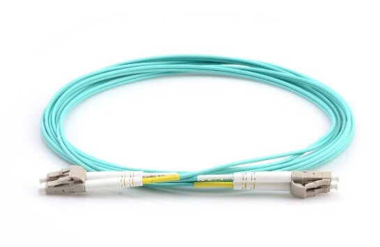
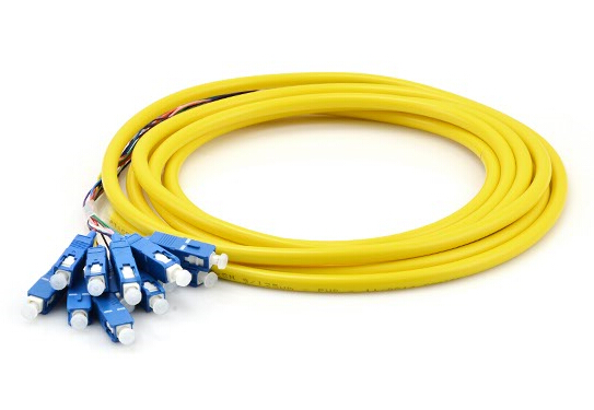
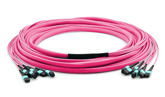
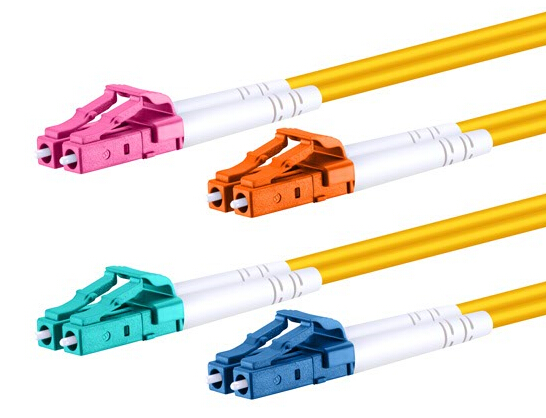
Fiber jumper is a fiber optic cable terminated with fiber optic connectors on both ends. It is often used to connect optical transceiver and fiber terminal box. Basically, it can be divided into single-mode patch cable (OS1, OS2) colored yellow, and multimode patch cable (OM1, OM2, OM3, OM4) colored orange or grey. According to the terminated connector, it can be same connector type patch cable, like LC to LC fiber patch cable, or hybrid fiber patch cable with different connectors on each end, such as LC to SC fiber patch cable. Fiber jumpers are featured by low insertion loss and high return loss, good repeatability and good interchange as well as excellent environmental adaptability. They are most employed to computer work station to outlet and fiber optic patch panels or optical cross connect distribution center.
single-mode& multimode fiber jumper

Ways to Inspect Fiber Jumper

There is no doubt that a well-performed fiber jumper is able to ensure high quality system connection, reduce network failure and identify the point of failure. And to achieve a better connection between fiber jumper and fiber coupler, the endface cleanliness of fiber jumper really matters since it directly affects the quality of network communications. There are also two ways to inspect the circumstances of fiber jumper endface.

Visual Inspection: Under normal circumstances the most common practice is to check the face dirt: disconnect the device and pick up the fiber jumpers against the light, by observing the side facing the bright light refraction to detect whether the end is clean and smooth. Through observation, if the side facing the light reflection is smooth and bright, then it is clean. if the side facing the light reflection is not too bright and not enough smooth, maybe there is dirt or there are scratches on the face. The endface of fiber jumper will seriously affect the quality of the optical transmission.

Instrument Checks: Among fiber jumper endface inspection tools, fiber optic microscope is the most widely used professional inspection equipment. When used in multimode fiber jumper, the microscope shows that ratio of 200 times, whereas used in single-mode fiber jumper, it shows that ratio of 400 times. With more advanced fiber optic microscope currently available on the market, one can test fiber jumper endface without disconnecting the equipment, meanwhile, it also avoids the risk of laser hurting eyes.  

Fiber Jumper Cleaning Methods

During the process of checking fiber jumper endface, contamination must be properly cleaned and removed to ensure high quality data link and communication. Since cleaning methods can vary from different maintenance personnel and circumstances, cleaning effects hence are not the same. However, if the conditions permit, it is advised to use professional cleaning tools to deliver better cleaning.

Cleaning Without Professional Tools

1. Clean cotton ball in one hand, and then ethanol drops on cotton balls.
2. With anhydrous alcohol cotton ball wiping down with the same direction, according to the severity of the end surface dirt.
3. Put a good face with an alcohol wipe three or more layers of the folded lens paper, to wipe face in the same direction until the alcohol is completely dry and the endface of the light reflection of bright reflective so far.
4. Carefully check the condition of the local light reflex face each and end face on fiber debris residues, if necessary, repeat the above step 1 to 3 until the end face clean and flawless.

Cleaning With Professional Tools

Here, we introduce the clean endface card to help clean the fiber jumper endface.

1. Tear plastic coverage on the cleaning belt.
2. Drop small drops of detergent to the cleaning belt.
3. Holding the fiber connector with the vertical direction, wipe from the wet to the dry.
4. Check again to ensure clean completely. If necessary, use a cleaner to clean it again according to the above steps.

Conclusion

As the fiber jumper is considered to be a vital component in fiber optic network, more importance should be attached to its performance and cleanliness. The inspection and cleaning method we offer are simple and feasible to conduct, besides, the routine operation and maintenance are also essential. After all, only these details are taken seriously, can a reliable and flexible communication environment be assured.

Upgrading Your Network With OM3/OM4 Patch Cable

As the demand for higher speed, reliability, manageability and flexibility of the network never ends, it is high time to upgrade your existing infrastructure in data centers. Therefore, more attention should be attached to fiber patch cable—one of the most vital components to ensure sound network environment. Currently, two types of multimode fibers—OM3 and OM4 patch cables have provided optimum choices to enhance network reliability and performance, which will be explained detailedly in following paragraphs.

OM3 and OM4 Patch Cable Overview

OM here refers to optical multimode, and multimode fiber has been widely employed in data centers nowadays since it presents a cost efficient option for short distance transmission. OM3 and OM4 are both laser-optimized multimode fibers with 50/125um core, which are designed for use with 850nm VCSELS (vertical-cavity surface-emitting laser) and are developed to accommodate faster networks such as 10, 40 and 100 Gbps. Compared with OM1 and OM2 patch cables, OM3 and OM4 patch cables are undoubtedly more suitable for today’s demanding networks as they enable data to transport at higher rate and longer distance. The following diagram clearly illustrates the performance of different multimode patch fiber.
OM3 and OM4 patch cable
Fiber Type 1G 10G 40/100G
OM1 300 m 36 m N/A
OM2 500 m 86 m N/A
OM3 1 km 300 m 100 m
OM4 1 km 550 m 150 m

The Advantages of OM3 and OM4 Patch Cable

The IEEE 802.3ba 40/100G Ethernet Standard was ratified in June 2010, which provides specific guidance for 40/100G transmission with multimode and single-mode fibers. According to the standard, OM3 and OM4 are the only multimode fibers included in it. And they are massively applied to upgrade the legacy infrastructure, especially for migrating to high-density networks. So, how can we exactly benefit from OM3/OM4 patch cables?

Get Higher Bandwidth

First and foremost, bandwidth is the main reason why OM3 and OM4 patch cables are used for network upgrades. OM3 and OM4 patch cables are optimized for 850nm transmission and have a minimum 2000 MHz∙km and 4700 MHz∙km effective modal bandwidth (EMB). Compared with OM1 and OM2 patch cables with the maximum 500 MHz∙km, advantages of OM3 and OM4 are obvious. With a connectivity solution using OM3 and OM4 cables that have been measured using the minimum EMB calculate technique, the optical infrastructure deployed in the data center will meet the performance criteria set by IEEE for bandwidth.

Get Longer Transmission Distance

The impact that transmission distance of fiber patch cables has on the data center cabling cannot be overestimate. And the manageability and flexibility will increase parallelly with longer transmission distance. OM3 and OM4 patch cables can support longer transmission distance compared with traditional multimode fibers. Generally OM3 fibers can run 40/100 Gigabit at 100 meters and OM4 fibers can run 40/100 Gigabit at 150 meters.

Get Lower Insertion Loss

Insertion loss has always been an essential factor to be considered during data center cabling. This is because the total connector loss within a system channel impacts the ability to operate over the maximum supportable distance for a given data rate. As total connector loss increases, the supportable distance at that data rate decreases. OM3 patch cable is specified to a 100m distance with a maximum channel loss of 1.9dB, which includes a 1.5dB total connector loss budget. And OM4 patch cable is specified to a 150m distance with a maximum channel loss of 1.5 dB, including a total connector loss budget of 1.0 dB. In this way, OM3 and OM4 patch cables help to achieve maximum flexibility and longer supportable transmission distance.

OM3 Patch Cable vs. OM4 Patch Cable

Apparently, OM3 and OM4 patch cables offer us an ideal alternative to upgrade the existing infrastructure. A question may occur to us is to determine which one is better. Well, it depends on several factors. Among which the applications and the total costs always serve as major ones.

Owing to the difference in the construction of fiber cable, OM4 patch cable has better attenuation and higher bandwidth of longer distance. Moreover, the cost for OM4 is higher than OM3. As 90% of all data centers have their runs under 100 meters, OM3 may be a better choice. However, considering future growth, the overall cost would come down with the increasing demand. In this case, OM4 might be the most viable option.

Conclusion

With either OM3 or OM4 patch cable, you are capable of upgrading the existing infrastructure to achieve more reliable and flexible network performance. Since they both provide us higher bandwidth, longer transmission distance and lower insertion loss. And when choosing between these two types of patch cables, your decision better be based on the current circumstances of the application and budget. Moreover, don’t forget to take future plan into consideration.

Sunday, August 28, 2016

Reference Guide to Optical Transceiver Testing

As an integral part of the entire network, optical transceiver plays a significant role in deciding the overall performance and reliability of the network. The importance of testing optical transceiver therefore cannot be overestimated. Currently, since an increasing number of optical transceivers employed in networks are provideed by third party suppliers, to ensure their compatibility and interoperability becomes more of a concern than ever. Well, this article is here to help you solve the problem.

Optical Transceiver Overview

Generally, an optical transceiver consists of a transmitter and a receiver. When a transmitter is connected with a receiver but the system doesn’t achieve your desired bit-error-ratio (BER), is there something wrong with the transmitter or the receiver? The transmitter and the receiver can affect each other, thus, specifications should guarantee that any receiver will interoperate with a worst-case transmitter, and any transmitter will provide a signal with sufficient quality such that it will interoperate with a worst-case receiver.

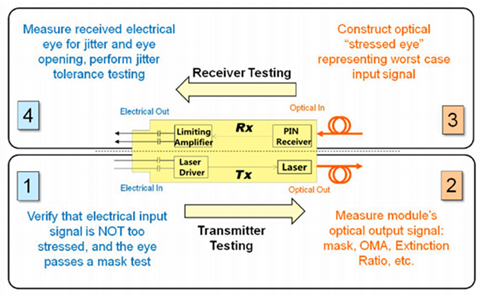
Precisely, defining worst case is often a complicated task. If a receiver needs a minimum level of power to achieve the system BER target, then that level will dictate the minimum allowed output power of the transmitter. If the receiver can only tolerate a certain level of jitter, this will be used to define the maximum acceptable jitter from the transmitter. In general, there are four basic steps in testing an optical transceiver, as shown in the following picture, which mainly includes the transmitter testing and receiver testing.
transceiver testing

Transmitter Testing

Transmitter parameters may include wavelength and shape of the output waveform while the receiver may specify tolerance to jitter and bandwidth. There are two steps to test a transmitter:

1. The input signal used to test the transmitter must be good enough. Measurements of jitter and an eye mask test must be performed to confirm the quality using electrical measurements. An eye mask test is a common method to view the transmitter waveform and provides a wealth of information about overall transmitter performance.
transmitter testing 1

2. The optical output of the transmitter must be tested using several optical quality metrics such as a mask test, OMA (optical modulation amplitude), and Extinction Ratio.
transmitter testing 2

Receiver Testing

To test a receiver, there are also two steps:

1. Unlike testing the transmitter, in which case one must ensure that the input signal is of good quality, testing the receiver involves sending in a signal of poor enough quality. In this case, a stressed eye represents the worst case signal shall be created. This is an optical signal, and must be calibrated using jitter and optical power measurements.
receiver testing 1

2. The last step is to test the electrical output of the receiver. There are three basic categories we should follow:
  • A mask test, which ensures a wide enough eye opening. The mask test is usually accompanied by a BER (bit error ratio) depth.
  • Jitter budget test, which tests for the amount of certain types of jitter.
  • Jitter tracking and tolerance, which tests the ability of the internal clock recovery circuit to track jitter within its loop bandwidth.
receiver testing 2

Conclusion

Complicated as it is, to test a fiber optic transceiver is also an indispensable step to ensure overall network performance. As basic eye-mask test offers an effective and commonly used option for testing the transmitter, testing the receiver can be more complex and requires more testing methods. A wide variety of fiber optic transceivers are available in FS.COM that are compatible with major brands on the market, such as Cisco, HP, IBM, Juniper, etc. Moreover, each fiber optic transceiver has been tested with the original-brand switch to ensure its high performance and superior quality. For more detailed information, please visit www.fs.com.

Do You Know Enough About Fiber Connectors?

As there exists a wide range of splice options for fiber network available on the market, selecting the right connector for your application can sometimes be tough and confusing. While choosing the fiber connector, various factors like cost and availability should be considered, which naturally lead to even less thought goes to connector itself. Since each connector has its own unique design as well as merits and demerits, it can pose a significant influence on deployment speeds and costs in the long run. So before making your decision, you’d better have an overall understanding of fiber connectors, and this is what we will talk about.

Fiber Connectors Overview

In this part, we will introduce some fiber connectors that are commonly used in the network applications. The following diagram directly explains the differences among them in performance.
Name Mating Cycles Ferrule Size Typical Insertion Loss (db) Application Features
SC 1000 2.5 mm Ceramic 0.25-0.5 Mainstream, Reliable, Fast deployment, Field fit
LC 500 1.25 mm Ceramic 0.25-0.5 High density, Cost effective, Field fit
FC 500 2.5 mm Ceramic 0.25-0.5 High precision, Vibration environments, Field fit
ST 500 2.5 mm Ceramic 0.25-0.5 Military (legacy), Field fit
MTP/MPO 1000 6.4*2.5 mm molded 0.25-0.75 High density, Aggregate networking, Fast deployment

SC Connector

SC connector was one of the first connectors presented on the market following the advent of ceramic ferrules. It has a push-pull coupling end face with a spring loaded ceramic ferrule. Initially intended for Gigabit Ethernet networking, it became increasingly popular as manufacturing costs came down. The SC connector has held a dominated position in fiber optics for over a decade with only the ST rivaling it. And it still remains the second most common connector for polarization maintaining applications. The SC is ideally suited for datacoms and telecoms applications including point to point and passive optical networking.
SC connector

LC Connector

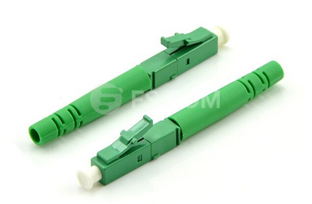
Considered to be the modern replacement of the SC connector, LC connector is also a push-pull connector, but it utilizes a latch as opposed to the SC locking tab and with a smaller ferrule it is known as a small form factor connector. LC connector shares huge popularity in datacoms and other high-density patch applications. And its small size and latch feature make it an ideal alternative for densely populated racks and panels. Since LC compatible transceivers and active networking components have been introduced, LC connector is likely to continue to grow steadily.
LC connector

FC Connector

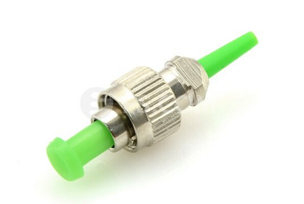
FC connector leads the trend to use a ceramic ferrule, but unlike the plastic bodied SC and LC, it utilizes a round screw-type fitment made from nickel-plated or stainless steel. In spite that the manufacturing and installation of FC connector are much more complex, it’s still an optimum option for precise measuring equipment such as OTDRs. Moreover, FC connector is particularly effective in high vibration environments, ensuring that the spring-loaded ferrule is firmly mated.
FC connector

ST Connector

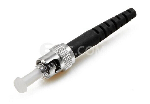
ST connector looks much like FC connector, but it uses a bayonet fitment rather than a screw thread. Deployed predominately in multi-mode datacoms, it is most common in network environments such as campuses, corporate networks and in military applications where the quick connecting bayonet had its advantages at the time. However, it cannot be terminated with an angled polish, which limits use in single mode fiber and FTTH applications.
ST connector

MTP/MPO connector

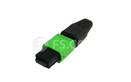
MTP and MPO connector falls into the category of multiple fiber push-on/pull-off connector. It is larger than other connectors since it can support up to 24 fibers in a single ferrule. It is currently extensively used in high density patch environments such as data centers, both at single mode and multi-mode wavelengths. MTP/MPO connector is often supplied with a fan-out assembly at the opposing end (such as LC, SC FC etc.). This allows the operator to change channels simply by re-patching the fanned-out side of the cable.
MTP/MPO connector

Conclusion

Getting to know the differences between various types of fiber connectors simply contribute to the primary stage of selecting the right one. And when it comes to the planning process of fiber deployments, the differences can be much more clearly. So, make sure to invest enough time to select the right fiber connector, which will do you a good return in the long run.

Sunday, August 21, 2016

Why Not Use QSFP28 Transceiver for Your 100G Network?

Service providers and enterprise data centers are undergoing an infrastructure transformation to achieve higher levels of performance and scalability that may explain why the demand for 100G network is always on the rise. Optical transceiver, therefore, is usually considered to be a vital component to ensure the flexibility and reliability of the whole system. 100G transceivers have become a preferable alternative for those bandwidth-hungry applications in data centers to accelerate data flow. In this article, we will introduce several 100G transceivers which are commonly seen on the market. And emphasis will be put on the 100G QSFP28 transceiver.

Common 100G Transceivers Overview

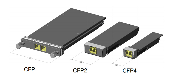
There exist 100G CFP transceiver, CFP2 transceiver and CFP4 transceiver on the market. The CFP transceiver comes out firstly. It was designed just after SFP interface, but it is significantly larger to support 100 Gbit/s data rates. While the electrical connection of a CFP transceiver uses 10 x 10 Gbit/s lanes in each direction (RX, TX), the optical connection can support both 10 x 10 Gbit/s and 4 x 25 Gbit/s variants of 100 Gbit/s interconnects.
With improvements in technology, CFP2 and CFP4 specifications have appeared to allow higher performance and higher density. Having similar electrical connection with a CFP transceiver, CFP2 transceiver and CFP4 transceiver specify a form-factor of 1/2 and 1/4 respectively in size of a CFP transceiver. These three modules are not interchangeable, but would be inter-operable at the optical interface with appropriate connectors.
100G CFP CFP2 CFP4

100G QSFP28 Transceiver Description

And here comes the dominate 100G transceiver—100G QSFP28 transceiver, which is implemented with four 25 Gbit/s lanes. With an upgraded electrical interface, QSFP28 transceiver is capable of supporting signal rates up to 28 Gbit/s, thus making it as easy to deploy 100G networks as 10G networks. Moreover, it has a strong ability to increase density, decrease power consumption, and decrease price per bit. With QSFP28, the way to migrate to 100G can change from 10G-40G-100G to 10G-25G-100G or 10G-25G-50G-100G, which can largely simplify the cabling in data center and effective decrease the cable density and the cost.

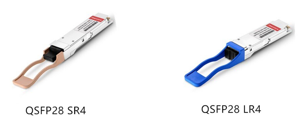
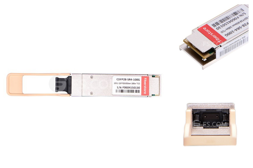
Basically, there are two types of QSFP28 transceiver: QSFP28 SR4 for short range transmission up to 100 m and QSFP28 LR4 for long range transmission up to 10 km. The following diagram illustrate some detailed information of each type.
QSFP28 SR4 vs.LR4
QSFP28 SR QSFP28 LR
Fiber Type Multimode Single-mode
Reach 100 m over OM3; 125 m over OM4 10 km over SMF
Transmission Type Parallel MM (4x25G) CWDM (4x25G)
Wavelength(s) 4 x 850 nm 1295 nm-1309 nm
Application Data Centers Data Centers; Carriers

What Can We Benefit From QSFP28?

Giving a look back to the evolution of 100G modules in the past few years, all these changes are closely related to factors like power and cost, which matters a lot to every data center and server room. Thus, the reason why 100G QSFP28 emerges is partly explained. Then, what exactly can QSFP28 bring to us?
100G QSFP28

Higher Port Density: The first generation of 100G transceiver is CFP, which is very large. When it comes to CFP2 and CFP4, the next generation of 100G modules, their sizes decrease a lot. With the same footprint and face plate density as QSFP+, QSFP28 is even smaller than CFP4, and its high port density is also an overwhelming advantage. Generally, up to 36 QSFP28 can be installed on a 1RU switch on the front panel.

Lower Power Consumption: Compared with other 100G transceivers, QSFP28 requires the lowest power for transmission, which could be less than 3.5 W. While for other 100G transceivers, the power consumption ranges from 6 W to 24 W.

Lower Cost: QSFP28 is able to save considerable amount of money with higher port density and lower power consumption. In addition, QSFP28, implemented with four lanes, increases the transmission capacity of every lane from 10G to 25G, which can effectively decrease cost for each bit.

Conclusion

With higher port density, lower power consumption and lower cost, QSFP28 offers an optimum and feasible alternative for 100G network data transmission, especially for those large scale data centers and carriers. Hope this article could assist you in choosing the right transceiver to achieve smooth migration to 100G.

Thursday, August 18, 2016

How to Choose Fiber Patch Cable for Your Transceiver?

It is generally accepted that fiber patch cable nowadays has captured a major and dominate place in the telecommunication industry. It offers a more appropriate way to transmit signal with higher performance and reliability. Fiber patch cable, together with optical transceiver, are claimed to be vital and indispensable to ensure smooth and valid data transmission, especially for links between the switches and equipment. However, selecting fiber patch cables for the transceiver module can sometimes seem like a daunting task since there exist various kinds of fiber patch cables. Is there any standard or criterion to consider? That’s what we intend to discuss in this article. But at the very beginning, let’s just review something rudimentary.

Basics of Fiber Patch Cable

Fiber patch cable, known as fiber jumper or fiber patch cord as well, is designed to interconnect or cross connect fiber networks within structured cabling systems. It is terminated with fiber connectors at both ends to be connected to an optical switch or other telecom equipment. Classified by fiber types, there are single-mode (OS1, OS2) and multimode (OM1, OM2, OM3, OM4) fiber patch cables, both are available with simplex and duplex transmission. While according to connector types, there are LC, SC, ST, FC and MTP/MPO fiber patch cables. Fiber patch cable usually features good repeatability, and interchange as well as excellent environmental adaptability.
Fiber patch cable

Basics of Fiber Optic Transceiver

Fiber optic transceiver, a self-contained component that allows for both transmitting and receiving signals. Usually, it is inserted in devices such as switches, routers or network interface cards which provide one or more transceiver module slot. During the transmission process, the electrical input can be converted to optical output to achieve fiber transmission. There are many optical transceivers types available on the market, such as SFP+ transceiver, X2 transceiver, XENPAK transceiver, XFP transceiver, SFP (Mini GBIC) transceiver, GBIC transceiver and so on.
Optical transceiver

Factors to Consider When Choosing Patch Cable

Since optical transceivers are capable of supporting higher and longer data rates, things can be more complicated when it comes to choose the right patch cable. So, before actually making your decision, here are certain aspects to consider: fiber type, transmission distance and data rate, and transceiver interface.

Fiber type and transmission distance: for optical transceivers, two types of fiber patch cables are used: single-mode (OS1, OS2) and multimode (OM1, OM2, OM3, OM4). Usually for short distance transmission up to 500 meters multimode patch cable is suggested, Whereas for long distance transmission, single-mode fiber patch cable is suggested.

Data rate: basically, as the transmission distance increases in a fiber optic cable, transmission data rate decrease. Compared with multimode, single-mode patch cords offer the best performance for different data rates in both long and short distances, but with higher cost. Therefore, for short distances data transmission with a limited budget, multimode fiber optic cable is likely to be a feasible and optimum option.

Transceiver interfaces: transceiver interface is directly connected to fiber patch cable, it usually uses one port for transmitting and one port for receiving. Generally, fiber optic transceivers usually employ duplex SC or LC interfaces. For BiDi transceivers, simplex patch cord is often adopted since it uses only one port for transmitting and receiving. Some 40G/100GBASE QSFP+ transceivers uses MTP/MPO interfaces, which should be connected to the network with multi-fiber patch cords attached with MTP/MPO connectors. If these ports are used for 40G to 10G or 100G to 10G connection, then fanout patch cable should be used. 
Transceiver interface

Real Case Analysis

In this part, let’s just take a real case for example, to explain how to implement we’ve discussed in reality.

Suppose that we need to choose a right patch cable using between Cisco fiber optic transceiver SFP-10G-SR and X2-10GB-SR. We know that SFP-10G-SR is the 10GBASE-SR SFP+ transceiver module for MMF, 850-nm wavelength, LC duplex connector. And X2-10GB-SR is the 10GBASE-SR X2 transceiver module for MMF, 850-nm wavelength, SC duplex connector. So that we would require patch cable with SC-LC connector with MMF, 850-nm wavelength. Likewise, we could choose right fiber patch cable for other transceivers.

Conclusion

Fiber patch cable is a key and indispensable component to achieve network flexibility and reliability, while choosing the right one for your transceivers, do not forget to take fiber type, transmission distance and data rate, as well as transceiver interface into consideration. This article simply offers you a reference guide, for more detailed product solution and tutorial, please visit www.fs.com.

Tuesday, August 16, 2016

Things to Know About BiDi Transceiver

In each and every data center and IT infrastructure, the demand for larger capacity, higher bandwidth and more reliable performance will never slack. Meanwhile, your applications and competitive advantages increasingly depend on it. Which may explain why nowadays migrating from 10G to 40G has become a popular and vital option for many service providers. This article will briefly introduce bidirectional (BiDi) transceiver—a cost-effective and feasible solution to bring 40-Gbps speeds to the access layer.

Introduction to BiDi Transceiver

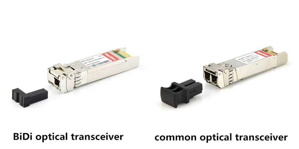
BiDi transceiver, also known as bidirectional transceiver, usually consists of two different wavelengths to achieve transmission in both directions on just one fiber (single-mode or multi-mode). Unlike general optical transceivers which have two ports, BiDi transceivers have only one port. With wavelength division multiplexing (WDM) technology, BiDi transceiver enables the signal to be sent and received in both directions by different center wavelength. The most frequently used wavelength of BiDi optical module is 1310nm/1550nm, 1310nm/1490nm, 1510nm/1590nm. From the picture shown below, it is easy to distinguish BiDi transceiver from the general one.
BiDi transceiver vs.general transceiver

Working Principle of BiDi Transceiver

The major difference between BiDi transceivers and general transceivers lies in the fact that BiDi transceivers are equipped with WDM couplers, which combine and separate data transmitted over a single fiber based on the wavelengths of the light. The following picture clearly illustrates how BiDi transceivers work. The two wavelengths that have been used in this example are 1310nm and 1490nm. Usually the upstream transmits at the shorter wavelength, while the downstream at the longer wavelength. What should be addressed is that BiDi transceivers must be deployed in pairs, so that the diplexers could turn to match the expected wavelength of the transmitter and receiver transmitting data.
BiDi transceiver working principle

What Can BiDi Transceiver Achieve
  • 40G connectivity becomes more reliable with BiDi transceiver technology. Your servers need it, your applications and users demand it, and your competitors are working to deliver it.
  • BiDi transceiver can reduce the cost in fiber cabling infrastructure since it requires less fiber cable and less fiber patch panels. On the other hand, BiDi transceiver also makes it possible to save more precious space in data centers.

QSFP BiDi Transceiver Solution

There exist three types commonly used BiDi transceivers: BiDi SFP+ transceivers, BiDi XFP transceivers and QSFP BiDi transceivers. As BiDi SFP+ transceivers and BiDi XFP transceivers are designed for bidirectional 10G serial optical data communications, QSFP BiDi transceivers allow reuse of existing 10G fiber infrastructure for 40G connections. In this part, we will discuss QSFP BiDi transceiver in detail.
40G QSFP BiDi transceiver has two 20G channels, each transmitted and received simultaneously on two wavelength over a single MMF strand (OM3 or OM4). It allows the existing 10G cabling system to be repurposed for 40G connectivity. Which means it lets you bring 40G speeds to the access layer using the same 10G cable plant you are using today. In contrast, the general QSFP SR4 transceiver like Cisco QSFP-40G-SR4 requires new patch cables and patch panels since the connector types differ and the size of the fiber trunk needs to be quadrupled.

40G QSFP BiDi transceiver

The QSFP-40G-SR-BD transceiver transmits full-duplex 40G traffic over one dual-fiber LC-connector OM3 or OM4 MMF cable. It is capable of reusing 10G fiber infrastructure. That’s to say it enables data center operators to upgrade to 40G connectivity without making any changes to the previous 10G fiber cable plant. It is a huge cost savings, whether you are upgrading your current data center or building a new one. And it means you can start taking advantage of 40G performance for your organization right now.

Conclusion

BiDi transceiver serves as an ideal and feasible solution in situations where only limited fibers or limited conduit space is available. And the deployment of BiDi transceivers efficiently enhances the bandwidth capacity of the existing optical fiber infrastructure and help to achieve economical and reliable performance of the optical network.

Friday, August 12, 2016

OSP Deployment: Ribbon Optical Cable or Loose Tube Optical Cable

Currently, the communication industry is increasingly reliant on high speed optical networks to support daily operations. It is a commonplace to see fiber optics being used in transmission lines and distribution lines, in generating stations, and even in substations. Since most of the fiber optic cables used in these situations are deployed in the outside-plant (OSP), more attention should be attached to the selection of the right optical cable. So, whether to choose ribbon optical cable or conventional loose tube cable in OSP deployment? Which one is more economically? This is what we will discuss today.

Introduction to Ribbon Optical Cable and Loose Tube Optical Cable
At the beginning, I’d like to give a brief introduction to ribbon optical cable and lose tube optical cable respectively.

Ribbon Optical Cable
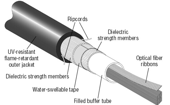
Ribbon optical cables provide an ideal choice for deployment in campus, building and data center backbone applications where fiber counts of more than 24 are required. Just like the stranded loose tube cable, ribbon optical cable offers robust performance as well. However, it is capable of accommodating the maximum fiber density relative to cable diameter. The cable design consists of 12 to 216 fibers organized inside a central tube and a non-flame-retardant jacket material is typically used in outside plant applications.
ribbon optical cable

Loose Tube Optical Cable
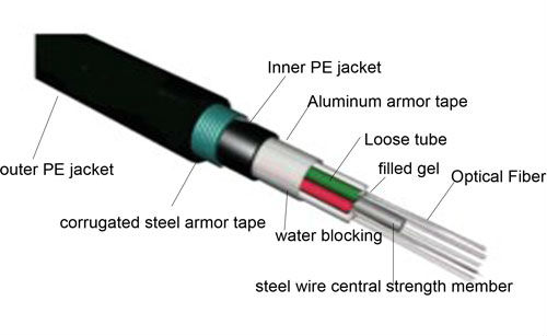
Loose tube optical cables are widely used for outside plant trunks because they offer exceptional and reliable protection for the fibers under high pulling tensions and can be easily protected from moisture with water-blocking gel or tapes. It typically consists of multiple buffer tubes that contain one to 12 fibers and are stranded around a central member. Contingent upon the deployment location, a non-flame or flame-retardant jacket is applied.
loose tube optical cable

Comparison Between Ribbon Optical Cable and Loose Tube Optical Cable
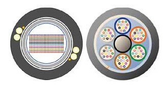
Both ribbon optical cables and loose tube optical cables are staples of the telecommunications industry. Both products perform well in harsh outdoor environments, and both are available in a multitude of configurations. However, the major differences between them lie in the manner in which the individual fibers themselves are packaged and managed within the cable. A ribbon optical cable has the individual fibers precisely bonded together, the number of which ranging from 4 to 24 fibers. Typically, they are bonded together in a group of 12 and placed inside a tube that holds multiple ribbons. In contrast, a loose tube optical cable design has between 2 to 24 individual fibers housed in multiple buffer tubes with each fiber detached from the other.
ribbon fiber cable vs.loose tube cable
Apparently, both ribbon optical cable and loose tube optical cable obtain some merits and demerits concerning different deployment scenarios, this will be explained in the next part.

Advantages of Ribbon Optical Cable
In some cases, it is better to adopt ribbon optical cable when the fiber counts hold a key issue. Since mass fusion splicing technology is enabled by ribbon optical cable, it can be spliced much more rapidly than loose tube cables. This advantage allows for less installation time, less installation labor cost, and significantly less emergency restoration time. Besides, It enables a smaller footprint in splice closures and telecommunications room fiber management. Ribbon optical cables offer greater packing density in higher fiber counts which enable more efficient use of limited duct space. And it is typically very cost competitive in counts above 96 fibers.

Advantages of Loose Tube Optical Cable
However, some applications such as fiber-to-the-home, require multiple cable access locations where we pull out only two to eight fibers from a cable for splicing using mid-sheath access techniques. In those instances, ribbon might be less practical for some carriers than conventional loose tube. There are still a few areas where either ribbon or loose-tube is the preferred option. For example, it takes four splices to repair a 48 fiber count ribbon cable compared to 48 splices for the loose-tube equivalent.

Conclusion
To conclude, there is not a single cable that fits all network designs perfectly and thoroughly. But it is essential to know the options and where they fit best, which may contribute to decrease installation time, labor cost, and emergency restoration time. Before choosing the optimum solution for the specific scenario, just remember to take cable costs, splicing costs and labor hours into consideration.

Thursday, August 11, 2016

Visually Locating Fiber Loss With VFL

As fiber links support higher speed network bandwidths with increasingly stringent requirements, it is becoming all the more important to ensure that your backbone links meet tightening loss standards. As network applications grow and expand, the need for higher data transmission capacity continues to grow as well. To guarantee reliable and efficient network connectivity and data transfer, the testing tool holds a key position in reducing the time spent identifying and locating the fiber loss. In this article, we will introduce an useful tool—visual fault locator (VFL) to achieve quicker, easier and more efficient fiber loss identification.

Introduction to VFL
VFL, also known as visual fault locator, serves as a fiber optic testing device that is widely used to locate the breakpoint, bending or cracking of the fiber glass. It can also locate the fault of OTDR dead zone and make fiber identification from one end to the other end. Designed with FC, SC and ST universal adapter, this fiber fault locator can be used without any other additional fiber adapters to locate fault up to 10 km in fiber cable. Featured by compact size, low weight and red laser output, the VFL is widely adopted to visually locate loss locations on fiber links and can also be employed to confirm fiber continuity.
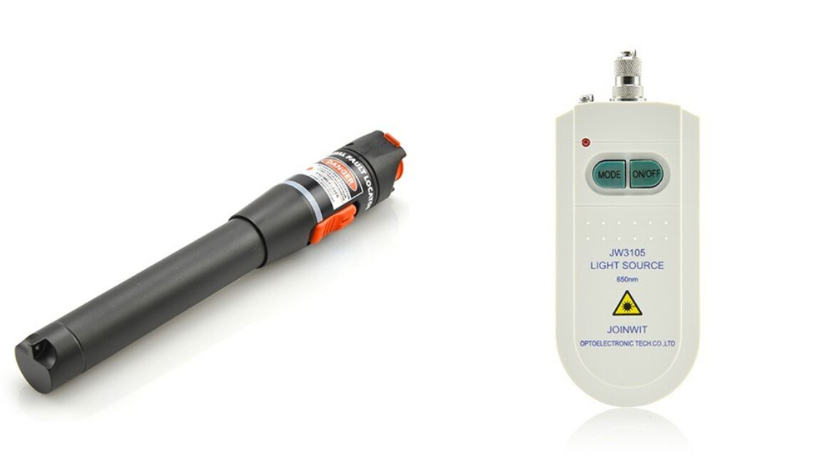
Generally, there exist two types of commonly used VFLs : pen shape visual fault locator and hand-held visual fault locator, the following picture shows the outlook of them.

Visual fault locator

How Does VFL Work?
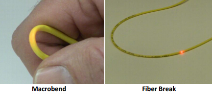
Since the light involved in transmitting signals over fiber optic is usually at 1300nm to 1650nm wavelength which is invisible to human, we can barely see it with our naked eyes. However, by injecting powerful visible light at 360nm to 670nm wavelength to the fiber, VFL helps to visually and directly locate the faults in fiber optic cable. This visible light keeps traveling along the core until it reaches a fault, then it leaks out, which can be seen through plastic coating and jackets. Thus, we can visually locate loss locations be it a macrobend, faulty connectors or a poor splice. In addition, VFL also helps to cover the range where optical time-domain reflectometers (OTDRs) are not useful because of the dead zone of the OTDR.

Fiber testing

Application of VFL
VFL is an ideal tool for locating defects that occur at connection and around fiber cabinets which are hidden in an OTDR “blind-spot” or “dead-zone”. Fiber breaks, faulty connector, sharp bends, bad splices and similar faults can be visually located by VFL. Visual fault locator can boost productivity in the field by providing fast detection, precise fault location, distance, loss, and ORL measurements.

Reference Guide to Use VFL
Network environments sometimes are too complicated for technicians to find the fault location, which makes visual fault locator a vital and indispensable tool for fixing the problem timely and precisely. The VFL is also used for conducting continuous tests and performing fiber identification. With visual fault locator, you can easily isolate high losses and faults in optical fiber cables. Here we offer you step-by-step procedures on how to use a VFL.
  • Step 1: Remove the plastic connector covers from both ends of the test fiber cable.
  • Step 2: Connect the fiber optic visual fault locator to one end of the fiber. Press the tester button and observe that light emanates from the other end of the fiber. This gives a simple indication of the continuity of the fiber link.
  • Step 3: Repeat with several other fibers. Check for light that can be seen leaking from a faulty splice. This may illustrate an easy way of carrying out visual fault finding on bad splices or joints.
  • Step 4: Disconnect all equipment, put the plastic covers back on the connector ends and return everything to the state it was before you started the practical, so the next group can carry out the practical in full.
VFL

What should be addressed is that during the testing process, you should never look into the output of VFL directly. After finishing the whole procedure, and remember to cover the VFL’s output with the dust cap.

Conclusion
Visual fault locator provides us a simple and convenient way to quickly locate faults in fiber optic cable, which is proved to be time saving and economical as well. Besides, it also alleviates the problems and pressures when dealing with massive fiber optic cabling system. Hope this article would help you get a better understanding of visual fault locator.

Tuesday, August 9, 2016

Things to Know About 40G QSFP+ AOC

As the demand for reliable, efficient and fast data transfer continues to heat up, the need for a more capable alternative to traditional copper cables also grows parallel with it. Achievements in network technologies have ushered in a new era with higher speed connectivity, thus migration from 10G to 40G nowadays is no longer a fresh topic but an irresistible trend. The active optical cable (AOC), since it was introduced in 2007, has been considered to be an optimum option for 40G support connectivity. This article will explain some vital elements in related to 40G QSFP+ AOC in detail.

40G QSFP+ AOC Description
40G QSFP+ AOC, as the name indicates, is a type of active optical cable used for 40G networks and applications. It is terminated with 40G QSFP+ connector on one end, and on the other end, it can be terminated with QSFP+ connector, SFP+ connector or LC connector etc. The QSFP+ optical modules provide four parallel full-duplex transmit and receive channels, each capable of 10Gbps operation and in total 40Gbps aggregate bandwidth of at least 100 m over multimode fiber.

With a bit error rate (BER) exponentially better than that of copper cables, along with being lighter and with a tighter bend angle, AOCs have since become mass-produced for data centers and server rooms all over the world.
40G QSFP+ AOC

How Does AOC Work?
The feature that distinguishes AOCs from traditional types of connectors is the fact that data passes through optical fiber lanes as opposed to copper, while maintaining a traditional electrical connectivity interface. Besides, optical cable possess a greater capability to carry a high-speed signal over longer distances than any other types of cable, without compromising signal integrity. Not to mention that it ensures data security and non-conductivity.

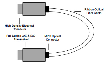
All active optical cables are comprised of four main functional parts:

1. High-density connector: The form factor of the connector equipped to either side of the optical fiber cable can come in many variants to fulfill a variety of functions, whether in QSFP+ format for data centers and server rooms or HDMI format for consumer entertainment.

2. Ribbon optical fiber cable: A multi-channeled optical fiber cable (that could come in multi or single-mode) ranging from 1 to 100 meters in length.

3. Full-duplex AOC transceiver: An optical transceiver is embedded into either side of the optical cable, two optical-electrical and electrical-optical converters on either side of the cable.

4. MPO optical connector: A connector that is permanently fixed to the form factor shell and fiber, designed to shield the optical interface from external interference.
Diagram of AOC

Comparison Between 40G QSFP+ AOC and QSFP+ Optics
Currently, 40G QSFP+ AOC is becoming increasingly popular in data centers, especially those are supposed to accommodate massive and high density bandwidth. Then, how dose 40G QSFP+ AOC differ from standard QSFP+ optics? And what we can benefit from employing 40G QSFP+ AOC? Here, we simply make a comparison between them from the perspective of total cost, insertion loss and return loss.

Cost—by adopting 40G QSFP+ AOC to your existing infrastructure, there is no need to use extra fiber patch cables. So, it generally costs less when compared with QSFP+ optic modules. Let’s just take QSFP+ to QSFP+ AOCs for example, it is usually employed to very short distance data transmission while offers a rather cost-effective way to establish 40G links between QSFP ports of switches within racks and across adjacent racks. Moreover, with 40G QSFP+ AOC, you will be free from cleaning the optical connectors as well as from termination plug and test when troubleshooting, which is time-saving and cost-efficient.

Insertion loss and return loss—when considering the repeatability and interchangeability performances within the same transmission distance, 40G QSFP+ AOC is superior to that of QSFP+ optics. Because when different fiber optic patch cables plug into the module, it will have the different insertion loss and return loss, which is the same even for the same module. However, an AOC is more stable and has better swing performance than other QSFP+ optics in this situation.

Conclusion
The 40G QSFP+ AOC is a high performance, low power consumption integrated cable for short-range multi-lane data transmission and interconnect applications. It has been widely used in high-density connectivity data centers to upgrade the current network equipment. 40G QSFP+ AOC also offers an optimum solution for high-performance computing and storage applications. So one can rely on 40G QSFP+ AOCs when designing for higher speed and more reliable network connectivity. For more detailed products information and interconnect solutions, please visit www.fs.com.

Friday, August 5, 2016

Achieve High Speed Connectivity With 40G QSFP+ DAC

The epidemic of switching and routing, cloud computing and virtualized servers is boosting the demand for higher network speeds, greater scalability, and higher levels of performance and reliability in data centers. Therefore, 1G and 10G are no longer capable of satisfying the increasing bandwidth needs, thus migration to 40G or 100G becomes an imperative and spontaneous alternation to cope up with the trend. This article will introduce 40G QSFP+ direct attach copper cable (DAC)—a cost-effective and ideal solution to support 40G applications.

What Is 40G QSFP+ DAC?
To make it easier to understand, we should figure out what DAC is at first. Direct attach cable (DAC) is a form of high speed cable with a transceiver shaped device on either end used to connect switches to routers or servers. DAC cables are not real optics and their components are without optical lasers, and it is much cheaper than regular optics. The low cost, low power consumption and high performances of DACs make it a favorable option for storage area network (SAN), data centers and high-performance computing connectivity.

Types of 40G QSFP+ DAC
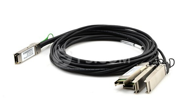
Generally, there exist three types of 40G QSFP+ DAC cables—40G QSFP+ to QSFP+ DAC, 40G QSFP+ to 4 SFP+ DAC and 40G QSFP+ to 4 XFP DAC.

40G QSFP+ to QSFP+ DAC
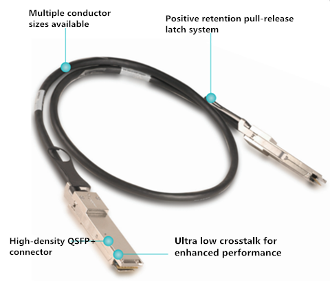
QSFP+ to QSFP+ DAC consists of a cable assembly that connects two QSFP+ modules respectively at each end of the cable. This kind of cable uses integrated duplex serial data links to ensure bidirectional communication. QSFP+ to QSFP+ DACs are usually employed in rather short distances and provide an efficient way to establish a 40G link between QSFP+ ports of QSFP+ switches with less cost.
40G QSFP+ to QSFP+ DAC

40G QSFP+ to 4 SFP+ DAC
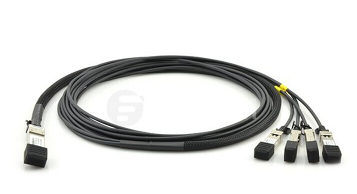
The migration from 10G to 40G Ethernet may be a gradual process. Which means it is possible that when you plan to deploy switches with 40G Ethernet ports, but the existing servers are still with 10G Ethernet ports. Then, QSFP+ to 4 SFP+ DAC are ready to solve the problem. These cables connect to a 40G QSFP port of a switch on one end and to four 10G SFP+ ports of a switch on the other end, which allows a 40G Ethernet port to be used as four independent 10G ports thus providing increased density while permitting backward compatibility and a phased upgrade of equipment.
40G QSFP+ to 4 SFP+ DAC
 

40G QSFP+ to 4 XFP DAC
The QSFP+ to 4 XFP DAC is not commonly seen as the former two types. It is a 40GBase QSFP+ hybrid passive cable with a QSFP+ connector at one end and 4 XFP connectors at the other. It’s an application for link with QSFP+ port on 40Gbps rate switch or host and feed up to 4 upstream 10Gbps switch or host.
40G QSFP+ to 4 XFP DAC

Advantages of 40G QSFP+ DAC
In all, 40G QSFP+ DAC provides inexpensive and reliable 40G speed connections and serves as an optimum choice to migrate from 10G to 40G Ethernet. The main advantages of QSFP+ DAC are listed below.
  • Enough data rate for various applications—DAC cables can support higher data rates than traditional copper interfaces. In fact, DAC cables can offer a highly cost-effective way to establish a 40G link between QSFP+ ports of QSFP+ switches within racks and across adjacent racks.
  • Interchangeability—With the advancements of copper cable technology, copper DACs are interchangeable and hot swappable with fiber optic modules.
  • Cheap—Since copper cables are much cheaper than fiber cables, DACs are cost-effective solution over optical transceivers and AOCs for short reach applications.
Conclusion
The deployment of 40G QSFP+ DAC cable to ensure higher speed and more reliable network performance is on the rise, meanwhile it also contributes to reduce the cost of short reach connectivity significantly. Implementing 40G QSFP+ DAC cable can be regarded as a win-win strategy to anyone who pursues high bandwidth without high expenditure.

LC Uniboot Fiber Patch Cable – An Optimum Cable Management Option

With the ever lasting advancement of networking technology, there comes an increasing demand for data centers to accommodate higher density cables and more bandwidth. However, it is generally acknowledged that data centers are often with limited space. Then how to handle those massive cables in such circumstances becomes a vital issue. This article will introduce the LC uniboot fiber patch cable, an optimum alternative for cable management that is designed to deliver maximum connectivity performance.

LC Uniboot Fiber Patch Cables Description
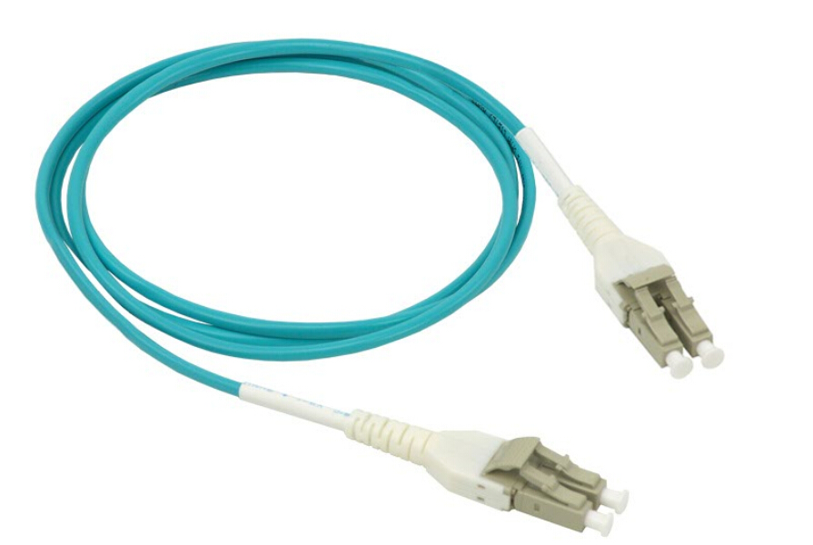
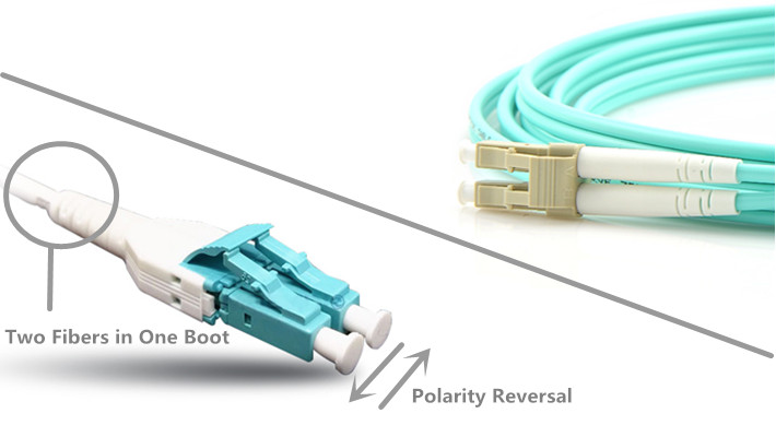
LC uniboot fiber patch cable consists of two LC connectors that wrapped by a common housing with one boot. It is terminated on a single, round, two-fiber cable to achieve duplex data transmission. LC uniboot patch cable allows for up to 68% savings in cabling volume due to a compact design, and it can ensure easier maintenance and operability with tool-less field reversible polarity and color identification. All the features presented by LC uniboot fiber patch cable make it an ideal option for high density network environment.
LC uniboot fiber patch cable

Comparison Between LC Uniboot Fiber Patch Cables and Standard Ones
LC fiber optic connectors offer higher density and better performance in most environments when compared with other fiber optic connectors, making it a reliable and popular choice for many applications and equipment. This can explain why uniboot fiber patch cables are terminated with specially designed LC connectors. The innovative LC uniboot fiber patch cable, with its unique structure and compact design, performs even better than standard LC fiber patch cables in high density cabling environment. Here, we present the obvious differences between the LC uniboot patch cable and the standard LC fiber patch cable in the following picture.
LC uniboot fiber patch cable vs.standard fiber patch cable

Features of LC Uniboot Fiber Patch Cables
Genarally, there are three primary features concerning the uniboot fiber patch cables:

Adjustable Pitch—the unique style of the clip allows the LC Connectors to easily adjust for the increasing demand of a 5.25 pitch, as well as the standard 6.25 pitch. Eliminating the requirement for hybrid patch cables.

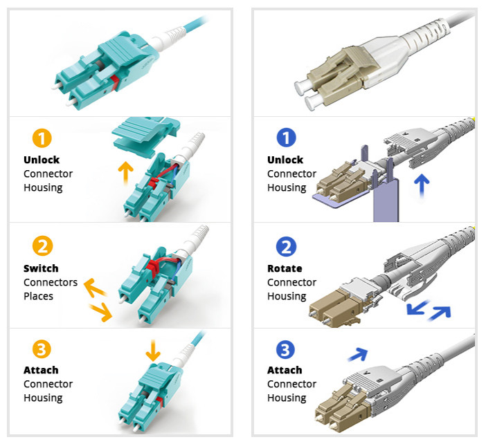
Reverse Polarity—with a few simple steps, the connectors polarity of the LC uniboot fiber patch cables can be reversed at will without connector re-termination.

Quick Release Latch—the latch of LC uniboot fiber patch cable allows for the quick and easy release of this connector from the adapter panel, which makes great sense in the growing trend of high density applications.

What LC Uniboot Fiber Patch Cables Can Achieve?
As we have mentioned previously, LC uniboot fiber patch cables are especially vital to space sensitive data centers and high density cabling environments, so what exactly we can benefit from deploying LC uniboot fiber patch cables?

Cable Congestion Reduction
With two fibers for duplex transmission firmly enclosed in a single cable, LC uniboot fiber patch cable effectively cuts down the cable count up to 50% compared with the standard LC duplex patch cords. Thus the space requirement of cabling can be significantly reduced by it, naturally result in less chance of cable congestion in data centers.

Effective Polarity Reversal
Changing the polarity of a standard LC duplex fiber patch cable may be annoying to many data center operators, especially when there happens to be a high density cabling system. This is sort of a time and energy consuming task since some minor mistakes could lead to various troubles. However, with LC uniboot patch cable, the polarity replacement can be much easier even without any additional tools. In terms of different types of LC uniboot patch cables, the polarity reversal steps may vary. We just illustrate two most used ones as follows.
LC uniboot polarity reversal

Conclusion
To address the increasing demand for high density applications and smaller fiber cable, the LC uniboot fiber patch cable is designed to help cut down cabling space and provide more effective polarity reversal solution, and to streamline cable management and logistics. Without doubt, LC uniboot fiber patch cable is the savior of popularized high-density cabling system. Hope this article could help you to choose the right LC uniboot patch cable for your applications, and for more products information and solutions, please visit www.fs.com.

Wednesday, August 3, 2016

40G QSFP+ LR4 Transceiver—An Ideal Choice for 40G Network

Applications and equipment in the network infrastructures and data centers are evolving dramatically, and these advancements would generate more bandwidth than ever. Apparently, multiple 10GbE links offer a common solution to achieve higher intra-rack bandwidth, however, as individual streams routinely reach 10Gbps speeds, it is necessary to have native 40GbE links to provide better performance. Thus, a cabling upgrade is required to ensure smooth migration to 40G network, while the 40G QSFP+ LR4 module is considered as an ideal and effective alternative.

General Description of 40G QSFP+ LR4 Module
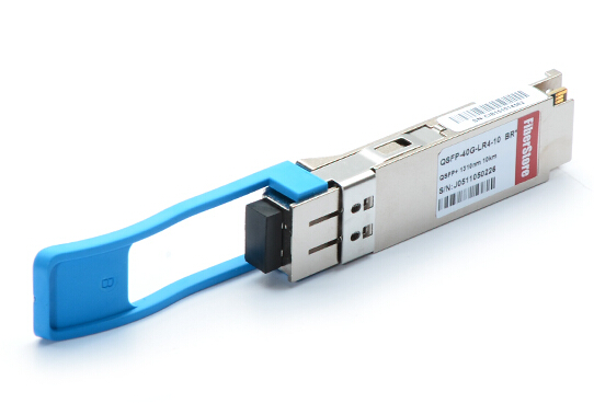
Before introducing the 40G QSFP+ LR4 module, let’s just take a glimpse of the 40G QSFP+ module firstly. A QSFP+ (quad small form-factor pluggable plus) module is the updated version of QSFP providing four 10-gigabit transmit and receive channels in a single pluggable optical module, for an aggregate bandwidth of 40 Gbps. QSFP+ module nowadays is widely adopted to provide high-density and low-power 40 Gigabit Ethernet connectivity options.
40G QSFP+ LR4 module is one of the common 40 Gigabit Ethernet connectivity options. It supports link lengths of up to 10 kilometers over a standard pair of single-mode fiber with duplex LC connectors. The letter "L" stands for long, the "R" indicates the type of interface with 64B/66B encoding and the numeral 4 means that the transmission is carried out over a ribbon fiber with four single-mode fibers in every direction, each of them has a 10 Gbps data rate.
40G QSFP+ LR4

How Dose 40G QSFP+ LR4 Function?
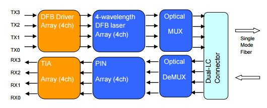
The 40G QSFP+ LR4 module converts 4 inputs channels of 10Gbps electrical data to 4 CWDM optical signals, and multiplexes them into a single channel for 40Gbps optical transmission.
To get a better understanding of the working process of 40G QSFP+ LR4 module, we can put it this way: the optical signal is combined by the MUX parts as a 40Gbps data, propagating out of the transmitter module from the SMF. The receiver module accepts the 40Gbps CWDM optical signals input, and de-multiplexes it into 4 individual 10Gbps channels with different wavelength. Each wavelength light is collected by a discrete photo diode, and then outputted as electric data after amplified by a TIA.
40G QSFP+ LR4 function

Installation Guide to 40G QSFP+ LR4
Like we have stated previously, 40G QSFP+ LR4 serves as an indispensable component for migrating to 40G network. It also brings much convenience and flexibility since one can install a QSFP+ LR4 module without powering off the system. But how to install it to your existing system? Here are some step-by-step procedures that may help.
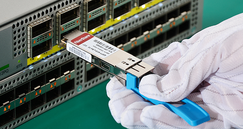
40G QSFP+ LR4 installation
1. Remove the QSFP+ LR4 module from its antistatic container and remove the dust covers from the module optical connector. If your module has a protective pad covering the card-edge connector, remove it. Store the antistatic container, dust covers, and card-edge connector protective pad in a clean location from which they can be easily retrieved if you need to uninstall the module.
2. Remove any rubber dust covers from the port where you are installing the QSFP+ LR4 module.
3. Holding the QSFP+ LR4 module by its sides, insert the QSFP+ module into the port on the switch or module.
4. Slide the QSFP+ LR4 module into the port until you hear it click into place.
5. Push up on the handle to secure the QSFP+ LR4 module in the switch.
Notice: QSFP+ modules contain Class 1M lasers. Invisible laser radiation can occur when laser connections are unplugged. Do not stare into the beam.

Conclusion
As 40G network has become an irreversible trend to accommodate greater bandwidths and ensure better performance, it allows of no delay to employ the efficient QSFP+ LR4 module to your data center infrastructures. FS.COM offers various of 40G QSFP+ LR4 modules compatible with the major brands on the market, such as Cisco, Juniper and Dell. All of them are fully tested to provide an end-to-end solution that is easier to maintain, helping improve the availability of data center networks. For more information, please visit www.fs.com.

Tuesday, August 2, 2016

How to Improve Network Security With Keyed LC Products?

One of the biggest challenges that service providers and network managers confronting today is to maintain data security throughout the enterprise. For there exist not only physical intrusion or tapping of the cables, but also non-contact eavesdropping. Any of these would pose significant threats to the whole network system. Apparently, although complicated software tools can detect, alert and respond to outside threats, it is easier to overlook physical security. The keyed LC or secure LC products present to be a desirable and ideal solution to efficiently reduce networking security risks, and the concerning details will be explained as follow.

The Importance of Securing Your Network
When talking about network security, let’s start by why this issue matters most in the information explosion era. The network is designed to send data back and forth, keeping us connected. And the purpose of network security is to protect the network and its components from unauthorized access and misuse. Many of the private networks consist of certain information that should not be shared with outside users on the web, or it may trigger devastated application layer attacks, IP spoofing, DNS cache poisoning, password attacks, and man in the middle attacks. It is hence natural that network security ought to be made as a top priority.
There is no doubt that network security system is an essential component of the configuration as well as network management. Implementation of effective network security products provides both physical and information security to paths, links, and databases.

Keyed LC Products Solution Overview
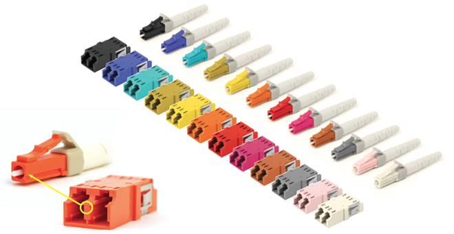
Facilities and infrastructures nowadays usually employ more than one network and need mechanical security to limit access and prevent inadvertent cross-connection. The most prominent feature of keyed LC products lies in their various colors, each of the different colors indicates one unique pattern, which means that only products with the same color can be connected to support the data link. Basically, there are 12 different keying options available for the keyed LC products, with each of them carries a different color to facilitate network administration.
Since keyed LC products contribute to much easier and effective identification and management due to their color-identification system, they are widely used in fiber optic networks. The relevant products include: keyed LC patch cords, keyed LC fiber optic adapters, keyed LC fiber adapter panels and keyed LC cassettes.

Keyed LC Patch Cords
The keyed LC patch cords are made in a variety of key colors and fiber types, designed to prevent accidental connection and ensuring physical network security. They can be adopted in both interconnect and cross-connect fiber networks. Keyed LC patch cords are available in single-mode 9/125 µm, multimode 62.5/125 µm, 50/125 um and laser-optimized 50/125 µm to cater for various requirements of the network.
keyed LC patch cable

Keyed LC Fiber Optic Adapters
The keyed LC fiber optic adapters are keyed on both the front and back to prevent installation errors and avoid a possible security breach. They are also color-coded for matching and available with single-mode and multimode applications.
keyed LC fiber optic adapter

Keyed LC Fiber Adapter Panels
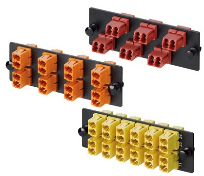
The keyed LC fiber adapter panels are considered to be a modular solution for restricted fiber cross-connect systems. Due to the unique color codes and keyed features, they are generally used to identify and manage restricted network cross connections. Currently, the existing keyed LC fiber adapter panels are available in 12 fibers, 16 fibers and 24 fibers.
keyed LC fiber adapter panel

Keyed LC Cassettes
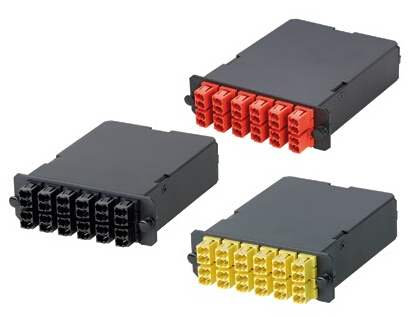
The keyed LC cassettes are designed to prevent unauthorized and inadvertent changes in highly sensitive applications such as data centers and secure IT networks. Horizontal fiber links from keyed LC cassette modules in the telecommunications room can be extended to keyed LC outlet fittings to provide restricted access to authorized users.
keyed LC cassette

Conclusion
As the internet evolves and computer networks grow dramatically, network security has become one of the most important factors for companies to consider. The keyed LC connectivity system was designed to respond to an urgent need for products that perform well for use in secure fiber networks. It offers great performance and reliability and can be installed very efficiently, you can count on the keyed LC products to ensure network safety.

Monday, August 1, 2016

Pre-Terminated Cabling System—An Ideal Solution for Data Centers

When designing and implementing their high-density networks, most data center managers and operators are inclined to options which are more sustainable and environmentally sound. They always expect systems to provide high performance and reliability for maximum network uptime over the long term. Since the demand for higher bandwidth and flexibility for future growth never ending, network administrators now are seeking to the network’s physical media infrastructure to achieve these goals. And the growing adoption of pre-terminated cabling system serves as one of the trend, that is what we will explain in this article.

What Is Pre-Terminated Cabling?
Then what the pre-terminated cabling system refers to and how it differs from field terminated one? In fact, pre-terminated cables go through the same procedures as field terminated cables, but these steps are taken at the manufacturer’s facility or cable assembly house and delivered to the job site with the connectors already terminated, properly polished, and the entire cable assembly tested on either both or one end. Which helps to eliminate the necessity for on-site field termination. Compared with field terminated cabling products, pre-terminated fiber cable assemblies are more convenient and flexible. They are most suited for network installations that are planned well in advance, taking into account both current and future requirements.

What Pre-Terminated Cabling System Can Achieve?
Installing and connecting your cable infrastructure in the data center consists of various labor intensive tasks. And manual field terminations, troubleshooting, and error corrections also extended deployment times, higher installation costs and increased downtime. However, with the deployment of pre-terminated cabling system, you are supposed to benefit from it with the following aspects:
  • Installation time and costs are substantially reduced.
  • Material reductions of 50 percent or more are typical when using pre-terminated systems rather than traditional systems.
  • Network performance and reliability are assured due to in-factory testing and validation of components.
  • Modular components at the physical layer are reusable. They can be disassembled and repurposed to accommodate moves, adds and changes, which provides greater flexibility and portability, as well as a clear migration path to support new technologies and applications as an organization grows and requirements change and evolve.
  • Pre-terminated installations are more precisely planned, which results in a neater, cleaner appearance, as well as faster and easier cable management, maintenance and troubleshooting.

Common Pre-Terminated Fiber Cables
It is undeniable that pre-terminated fiber cabling system indeed offers a constructive and ideal solution to data center management and maintenance. Here in this part, we will further introduce some most commonly employed pre-terminated fiber cables, including fiber patch cables, fiber optic pigtails and MTP/MPO pre-terminated cables.

Fiber Patch Cables
As one of the most used components in fiber optic networks, fiber patch cables help to ensure a reliable temporary fiber optic interconnection. There exists a wide range of fiber patch cables on the market, available in single-mode and multimode versions with PVC, LSZH, OFNP or armored jacket. And connection type options involve LC, FC, SC, ST, MU, MTRJ and E2000 pre-terminated in duplex or simplex fiber. Fiber patch cables are suitable for all kinds of fiber optic connectivity applications.
fiber patch cable

Fiber Optic Pigtails
Fiber optic pigtail, which is a fiber optic cable of a specified length, has only one end terminated with the appropriate connector style and an open unterminated end. A pigtail can be fusion spliced onto a pre-terminated fiber optic cable assembly to extend the cable distance or onto field-terminated cables to provide the connectorized end. Pigtails do not need the same configuration or connector style as the opposite end. Keep in mind that when installing pigtails, you must be trained and will need additional equipment, such as a fusion splicer and fusion splice trays.
fiber optic pigtail

MTP/MPO Pre-Terminated Cables
Pre-terminated with high-quality and low loss MTP/MPO connectors, this kind of cable can meet the high-speed, high-density, and wide bandwidth demands of the current and future network. Basically, both MTP/MPO trunk cables and MTP/MPO harness cables are classified into this category. They are available in any fiber mode (single-mode, multimode and 10G multimode) and a full range of length options.
MTP/MPO trunk cable

Conclusion
Pre-termination cabling is not just a popular trend, it is an increasingly popular way of delivering a project in a more timely and cost effective manner. Which on the whole can provide benefits for all sizes of project.