Thursday, June 30, 2016

Introduction to Automatically Switched Optical Network (ASON)

Optical backbone networks which based on SDH/SONET and WDM technologies are designed mainly for voice applications. However, it gradually fails to satisfy current needs triggered by rapid growth of data traffic. Thus, resources available to users often cannot be allocated properly because of the inherent inflexibility of manually provisioned large-scale optical networks. While with the advances in optical component technology, a significant amount of attentions are attached to the emerging technology of Automatically Switched Optical Networks (ASON), which enables more dynamic and diversified networking that may change the network characteristics dramatically.

Definition of ASON
As its name indicates, an Automatically Switched Optical Network (ASON) is an “intelligent” optical network that can automatically manage the signaling and routing through the network. However, in traditional network backbone, it was rather necessary to configure cross-connections in the network elements, an optical switch for example, to create a new traffic path for a customer. ASON is an optical transport network with dynamic connection capability, and this capability is achieved by using a control plane that performs the call and connection control functions. ASON aims to automate the resource and connection management within the network.
ASON uses the Generalized MPLS (GMPLS) signaling protocol to set up and monitor edge-to-edge transport connections. Switching technologies used in ASON range from single fiber switching to wavelength switching and to optical packet switching. And the components required for the switching are optical cross connects (OXCs), wavelength converters and optical add/drop multiplexers (OADMs).

Importance of ASON in Optical Network
In an optical network which is not based on ASON technology, when it comes to the need for more bandwidth, a new connection may be required. Thus the service provider must then manually plan and configure the route in the network, which is proved to be time-consuming. Moreover, it would waste a lot of bandwidth thus to cause inevitable problems to the whole network since bandwidth is increasingly becoming a precious resource. And the optical networks in the near future bear expectations to efficiently handle resources. ASON can fulfill some of these requirements for optical networks, which are listed below:
  • Fast and automatic end-to-end provisioning
  • Fast and efficient re-routing
  • Support of different clients, but optimized for IP
  • Dynamic set up of connections
  • Support of Optical Virtual Private Networks (OVPNs)
  • Support of different levels of quality of service
What should be noticed is that these requirements are not restricted to optical networks but can be applied to any transport network.

Architecture of an ASON
The layered transport plane, also referred to as data plane, represents the functional resources of the network which conveys user information between location. Transfer of information are either bi-directional or unidirectional. The transport plane can also provide transfer of some control and network management information.
Basically, the logical architecture of an ASON can be divided into 3 planes: transport plane, control plane and management plane.
The transport plane contains a number of switches, and these switches can either be optical switch or other types. Which are responsible for transporting user data via connections. These switches are connected to each other via physical interface (PI).
The control plane is responsible for the actual resource and connection management within an ASN network. It consists of a series of optical connection controllers (OCC), interconnected via network to network interface (NNIs). These OCCs have the following functions:
  • Network topology discovery (resource discovery)
  • Signaling, routing, address assignment
  • Connection set-up/tear-down
  • Connection protection/restoration
  • Traffic engineering
  • Wavelength assignment
The management plane, on the other hand, is responsible for managing the control plane. Its responsibilities include configuration management of the control plane resources, routing areas, transport resource in control plane and policy. It also provides fault management, performance management, accounting and security management functions. The management plane contains the network management entity which is connected to an OCC in control plane via the network management interface for ASON control plane (NMI-A) and to one of the switched via network management interface for the transport network (NMI-T).
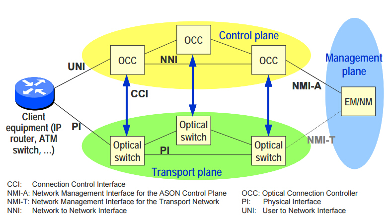
ASON architecture

Conclusion
To sum it up, ASON can help to meet user requirements on a more realistic economical basis without resource consuming over-provisioning. Moreover, it also contributes to offering a good platform to realize a more cost-effective networking environment. I hope what presented above would help you to have a better understanding of ASON.
Fundamentals of FTTx Network

The telecommunication industry nowadays has ushered in various new and advanced services that changed human life dramatically. With the demand for higher bandwidth consistently on the rise, an increasing number of service providers endeavored to provide a one-stop shopping service to cater to customer’s requirements. FTTx technology has proved to be viable and effective network solution.

Definition of FTTx Network
FTTx is a general term referring to describe fiber-based access networks, and the x could be H (home) if the fibers are terminated at the home of the subscriber; x could also be B (business), if the fibers are terminated at an office building. In addition to these two types, there also exist common ones like FTTC (Fiber-to-the-Curb) and FTTN (Fiber-to-the-Neighborhood).
It is generally accepted that compared to copper or digital radio, fiber features higher bandwidth and lower attenuation. FTTx technology enables users to get more extensive bandwidth and enjoy more diversified services at home by installing optical fiber all the way to subscriber. It is hence natural that FTTx technology is rather prevalent throughout the world.

Deployment Scenarios of FTTx Network
Just as what we have mentioned above, the fiber can be terminated at the user’s premises, a block of apartments or offices in a FTTx network. In some scenarios the optical fiber can be laid all the way to the subscribes’ premises such as FTTH, whereas in others, fiber optics may be terminated at either a place or node close to groups of subscribers, which depends on several factors. In this part, we will explain some common deployment scenarios.

FTTH (Fiber-to-the-Home)
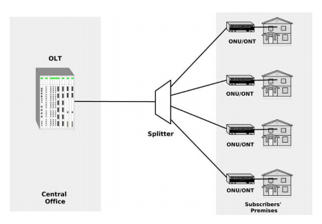
In FTTH deployment, the fibers are being laid from the central office (CO) to each house or apartment. As a house or a home is usually occupied by a family, it is frequently referred to as a single dwelling unit (SDU). The following picture shows the FTTH deployment scenario.
FTTH

FTTB (Fiber-to-the-Building)
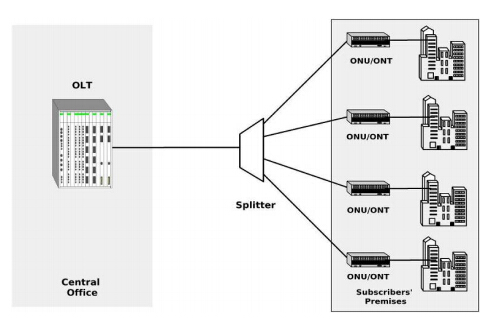
Likewise, FTTB is a deployment scenario where the fiber is laid directly from the CO to an office or private apartment with multiple business tenants or homes. And the term Multiple Tenant Unit (MTU) is frequently used to those tenants or apartment units. The ONT in this scenario is often connected to an Ethernet switch that used to link all the tenants within the same building. Moreover, while in FTTB deployment, there is no need to replace the existing copper LAN cables in the building for optical fibers.
FTTB

FTTC (Fiber-to-the-Curb)
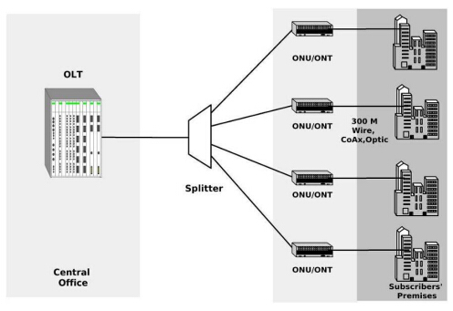
In FTTC deployment scenario, however, the fiber is laid from the CO to an optical network unit (ONU) or optical network termination (ONT) that is located within 300 m from office building or home. Instead of optical fiber, in FTTC scenario we often use transmission medium such as twisted pair cable or coaxial cable to achieve connection to the subscribers.
FTTC

FTTN (Fiber-to-the-Neighborhood)
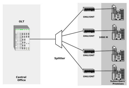
FTTN is a deployment scenario where fiber from the CO is terminated at a communication switch located within 1 km from office buildings or homes. FTTN can contribute to save a significant amount of cost since one can use the existing coaxial or twisted pair infrastructure to provide the final physical connection to the end users.
FTTN

FTTx Network Application
FTTx effectively and efficiently provide users triple play, which is a standard mix of traffic types known as voice,video and data. Traditional subscribers must connect to three different networks and service providers for their phone service, video broadcast and the Internet. However, once adopting FTTx, all of these types can be integrated into a single fiber network just by using different wavelengths. Hence, on the basis of triple play service, the FTTx network can thus be applied to IP telephony, video on demand (VOD), IPTV, interactive games, telepresence, video conferencing, and externally monitored home security. To this end, service providers need to offer bandwidths of 50 to 100 to enable subscribers using these services.

Conclusion
In conclusion, FTTx network is a popular tendency in current telecommunication industry since it offers a better networking experience and more convenience for subscribers. The article simply describes some rudiments of FTTx technology, for more information concerning the FTTx solution, visit Fiberstore at www.fs.com. We provide professional FTTx solutions and tutorials for your infrastructure.

Monday, June 27, 2016

MEMS Optical Switch Analysis

With the increasing prevalence of the Internet and modern communications around the world, fiber optics, which signifying a significant information revolution in the telecommunication industry—are racing to keep up. The rapid growth of data transmission worldwide is driven by the existing demand for high quality Internet service. Meanwhile, software developers and users are constantly employing applications that take up more and more bandwidth in order to enhance the speed of information delivery, which, without doubt, placing heavy burdens on fiber networks. So carriers are looking for innovative ways to push more data through existing fiber.
To this end, there come various vital advancements in network communication that efficiently exploiting and extending the capacity of current fiber optic systems in significant ways, and optical switching captures an essential position among them.

What Is Optical Switching?
The backbone of telecommunications and networking today is the “all-optical network”, which means every communication would remain an optical transmission from start to finish. However, a certain amount of networking equipment today is still based on electronic signals, that is to say, the optical signals have to be converted to electrical ones, then to be amplified, regenerated or switched, and reconverted to optical signals. This process is referred to as an “optical-to-electronic-to-optical” (OEO) conversion. Which is considered to be a significant bottleneck in transmission. Therefore, huge amount of information traveling around an optical network needs to be switched through various points known as nodes.
Optical switching functions by replacing existing electronic network switched with optical ones, making no need for OEO conversions. It contributes to lower cost and physically smaller switches as well. However, optical switching technology currently is still immature, thus several ideas have been proposed as to how to implement light switching between optical fibers, among which the most common technique is that of the tiny movable mirrors known as micro-electro-mechanical systems (MEMS).

Introduction to MEMS
While the widely use of micro-electro-mechanical systems (EMES) in some other industries is nothing new, its adoption for telecom applications is relatively recent.
Conventional MEMS works by reflecting the beam of light from the surface of a tiny mirror. MEMS systems have moving parts, and the speed at which the mirror moves is limited. By applying more current, the mirror can move faster, but there's a limit to how much current can be sent into the array of mirrors. If this weren't bad enough, it seems that the speed and angular displacement terms in the calculation of the required current have integer powers of around 4 or 5, and so the bottom line is that we have to put a lot of current into the array for a small improvement in speed. By changing the mirror design so that the angle through which light is bent is smaller, it's possible to achieve faster switching speeds. This technique is known as "fast MEMS."

MEMS Switches Overview
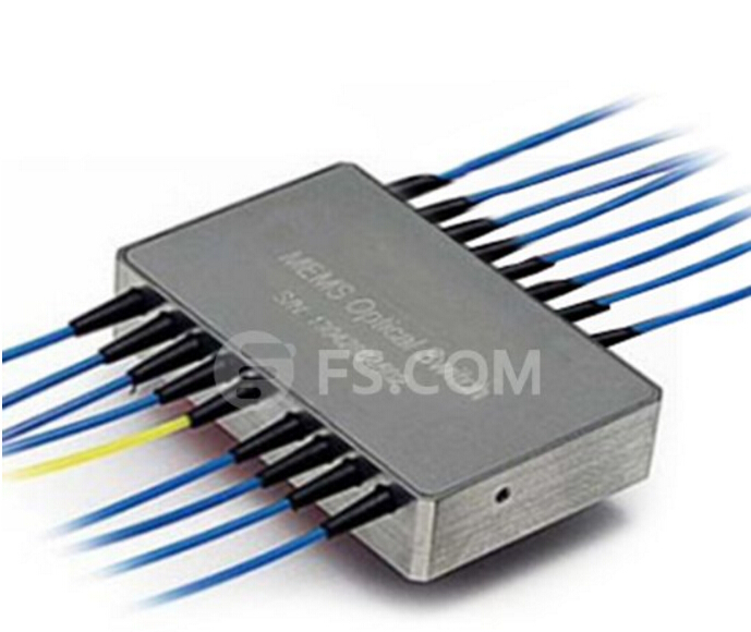
MEMS optical switch is a micro-optical switch that made of the semiconductor material, which is generally used as movable micro-mirrors that can deflect optical signals from input to output fibers. It embraces the advantages as compact, lightweight and easy to expand. Besides, it shares the merits of both the mechanical optical switch and wave guide optical switch. Since EMES combines the electrical, mechanical and optical integration as a whole, it can apparently transmit different rates and different business services. MEMS switches feature good scalability. Two-dimensional arrays with size 32x32 are already available and can be used as basic building blocks, in single-stage architecture, to scale up to 256 ports.
MEMS switch

Conclusion
Although MEMS still persists some drawbacks—too slow for optical burst switching or optical packet switching applications, the technique of it is under improving and progressing. Since it seems to have a monopoly on the high port-count optical switch market for the moment, a huge amount of investment is going into the implementations and into solving the basic problems.

Friday, June 24, 2016

Fiber Optic Termination Overview

When installing a fiber optic network, appropriate fiber optic termination is considered to be an extremely important part since it can affect the performance and reliability of the whole network. It is hence natural that much attention should be necessarily attached to this area nowadays. Besides, an increasing number of products concerning fiber optic termination are appearing on the market to make the termination task easier and more accurate. The article will make an overview of fiber optic termination.

What Is Fiber Optic Termination
Generally speaking, fiber optic termination acts as the connection of fiber or wire to a device, the device can be something like a wall outlet or equipment that allows for connecting the cable to other cables or devices. Based on this, fiber optic termination enables fiber cross connection and light wave signal distribution. Proper fiber optic termination is able to meet the demand for protecting the fibers from dirt or damage while in use and preventing excessive loss of light as well, which also contribute to smooth and efficient performance of the network.

Preparing for Fiber Optic Termination
Before performing fiber optic termination, one should get well-prepared to ensure a smooth and successful process of termination. The preparation for fiber optic termination involves several steps: gathering the supplies you need, stripping the outer jacket, cutting the kevlar, and stripping the buffer or coating. For supplies, you’ll need safety glasses, a fiber disposal bin, connectors, fiber optic cable, epoxy and syringes (or anaerobic adhesive), and polishing film. Tools used in fiber optic termination usually include fiber stripper, scribe, aramid yarn scissors, adjustable cable jacket stripper, polishing puck, polishing glass plate, and a rubber pad to polish the PC connectors, especially for single mode termination. Besides, You’ll also need to test equipment such as a power meter, FO tracer, reference test cables, a LED light source and a microscope to view the connector.

Methods of Fiber Optic Termination
It is commonly believed that fiber optic termination is often time-consuming and highly specializes. However, due to the continuous advancement in termination technology, fiber termination systems currently demand less training and produce higher quality fiber connections in less time.
Basically, three widely adopted fiber termination methods are available to operators: pre-polished connectors, epoxy and polish fiber termination and pigtail connectors.

Pre-polished Connectors
Pre-polished connector has a short length of fiber already installed into the ferrule by the manufacturer of the connector. Moreover, the manufacturer also polished the ferrule end face thus there is no need to carry out this step on-site. The fiber to be terminated must be prepared using a specialist cleave tool and inserted into the rear of the connector where an index matching gel is often used to bridge the gap between the two fibers. The terminated fiber is held in place using some form of crimp or locking mechanism on the rear of the connector.

Epoxy and Polish Fiber Termination
This type of connector requires the application of some form of epoxy (glue) between the fiber and the connector ferrule that firmly bonds the two elements together once the epoxy has dried. There are a number of different types of epoxy available:

Heat Cured Epoxy — uses some form of “oven” to cure the epoxy, which can be selected for the optimum performance within pre-determined temperature ranges. The epoxy may either need to be injected in to the ferrule by the technician or the connectors may be supplied with the epoxy already injected by the connector manufacturer.

Ambient Temperature Epoxy— cures at room temperature without the need for any power, making it suitable for on-site terminations.

Fast Acting (Anaerobic) Adhesive — use an accelerant to speed the curing time. It can cause problems if the technician is unable to complete the insertion of the fiber into the ferrule before the epoxy cures.

Pigtail Connectors
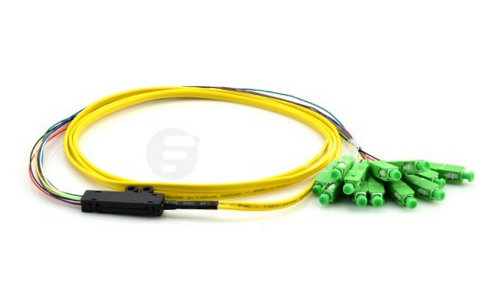
Splice-on connectors are an alternative to either the pre-polished connector systems or the epoxy method of termination. A pigtail is a short length of 900 micron buffered fiber that has been factory terminated with a fiber optic connector. Thus it eliminates the need for any on-site termination or polishing of the connector. Splicing the end of the fiber of the pigtail to the end of the fiber of the cable, the pigtail is then attached to the cable. Fusion splicing is a preferred splicing method, where the two fibers are melted together using a high powered electric arc, forming one, single, continuous strand of glass.
Pigtail
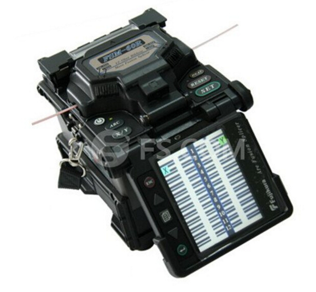
Fusion splicing often requires the use of precision fiber cleaving tools and a fusion splicing machine. The fusion splice machine is used to align the two fiber end faces automatically and fuse the two together to create a very low loss joint.
Fusion splicer

Conclusion
Since fiber optic termination is an indispensable part of the optical network installation, we should always keep in mind the importance of it and get fully prepared before performing the task. Moreover, selecting a proper and efficient termination method could also help to ensure the excellent performance of the network.

Introduction to Optical Add-Drop Multiplexer (OADM)

There exist several different channel routing technologies in the field of optical communications. However, the evolution of single wavelength point-to-point transmission lines to wavelength division multiplexed optical networks has introduced a demand for wavelength selective optical add-drop multiplexers (OADM) to separate or route different wavelength channels. This article provides some fundamentals relevant to OADM.

What Is OADM?
Optical add-drop multiplexer (OADM) is a device used in wavelength-division multiplexing (WDM) systems. "Add" and "drop" is a capability device to add one or more new wavelength channels to an existing multi-wavelength WDM signal or to drop, which means to remove one or more channels, passing those signals to another network path. OADM can be used at different points along the optical link to insert, remove or route selected channels thus to increase the network flexibility. OADM is particularly important in metropolitan WDM light wave services where offices or sited can be connected by different add-drop channels.
A traditional OADM consists of three stages: an optical demultiplexer, an optical multiplexer, and between them a method of re-configuring the paths between the demultiplexer, the multiplexer and a set of ports for adding and dropping signals. The demultiplexer separates wavelengths in an input fiber onto ports. The reconfiguration can be achieved by a fiber patch panel or by optical switches which direct the wavelengths to the multiplexer or to drop ports. The multiplexer multiplexes the wavelength channels that are to continue on from demultiplexer ports with those from the add ports, onto a single output fiber.

The Functions of OADM
As we have mentioned above, the main function of an optical multiplexer is to couple two or more wavelengths into the same fiber. If place a demultiplexer and properly aligned it back to back with a multiplexer, there would exist two individual wavelength in the area between them. Then, this offers a chance for an enhanced function that individual wavelengths could be removed and inserted as well. The function would be called an optical wavelength drop and add demultiplexer/multiplexer—to make it briefly, optical add-drop multiplexer.
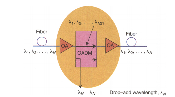
The model of an OADM is clearly shown in the picture below, where F1 signifies a filter selecting wavelength λ1 while passing through all other wavelength, and M1 signifies a multiplexer that multiplexes all wavelengths.
OADM
An even better view of OADM function is shown in the following picture. This function is often employed in WDM ring systems as well as in long-haul with drop-add features.
OADM-WDM

Types of OADM
There are two main types of OADM that can be used in WDM optical networks: fixed OADMs that are used to drop or add data signals on dedicated WDM channels, and re-configurable OADMs that have the ability to electronically alter the selected channel routing through the optical network.
The fixed optical add-drop multiplexer (FOADM) is a traditional wavelength arrangement scheme that can only input or output a single wavelength via the fixed port. FOADMs have pre-assigned channels at static nodes and allowed adding and dropping of individual or multiple wavelength channels from a DWDM.
The re-configurable optical add-drop multiplexer (ROADM), on the other hand, is a dynamic wavelength arrangement scheme, allows for dynamic wavelength arrangement scheme using a wavelength selective switch (WSS). The 8-dimensional cross-connect provided by the WSS enables quick service start-up, remote cross-connect and WDM mesh networking. The ROADM scheme can also achieve inputting/outputting a single wavelength or wavelength group via the fixed port. ROADM can add, block, pass or redirect modulated infrared (IR) and visible light beams of various wavelengths in a fiber optic network. Which featured by providing flexibility in rerouting optical streams, bypassing faulty connections, allowing minimal service disruption and the ability to adapt or upgrade the optical network to different WDM technologies.

Conclusion
To summarize, OADM plays a vital role in improving and optimizing the network performance and reliability. And it is fully compatible with both local area network (LAN) as well as long haul networks. Moreover, OADM also serves as an essential device to meet the requirement of the rapidly developed network.

Monday, June 20, 2016

Local Area Network (LAN) Analysis

Networks can be defined as a collection of independent computers and other devices interconnected by a communication medium. A network usually consists of two or more computers that are linked in order to share resources like printers and CDs, exchange files, or allow electronic communications. The computers on a network may be linked through cables, telephone lines, radio waves, satellites, or infrared light beams. There exist various types of networks, including Local Area Network (LAN), Wide Area Network (WAN), Metropolitan Area Networks (MAN), Wireless LAN (WLAN), or Wireless WAN (WWAN). Among them the LAN and WAN are the most common types. This article will give a basic introduction of LAN.

What Does LAN Mean?
A local-area network (LAN) is a computer network that spans a relatively small area. It is a group of computers and associated devices that share a common communications line or wireless link to a server. Typically, a LAN encompasses computers and peripherals connected to a server within a small geographic area. Computers and other mobile devices can share resources such as a printer or network storage. Most often, a LAN is confined to a single room, building or group of buildings.
LANs can be distinguished from other networks because of their short distance. The total coverage may be from 1 km to 10 km. The data transmission speed of LANs is much higher than in other types of networks. Besides, the error rate in data transmission is slow because of the shorter distance between the equipment. Since LANs are within a single building or a smaller area, they are owned by the specific organization. This localized control provides greater flexibility in LANs than other types of networks.

Components of LAN
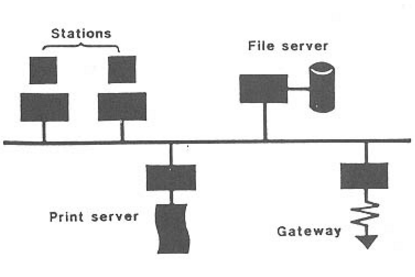
Each workstation of the LAN can be a microcomputer, but they are connected to a central controlling unit, through which they can exchange data, share software or hardware with other workstations of the network. Though each workstation can act independently, they are not capable of controlling the activities of other stations of the network. Then, let’s just take a look at the basic components of a LAN which are shown in the following picture.
Components of LAN
  • Communication medium: there is some kind of medium to connect all the workstations and other equipment together.
  • File server: a computer dedicated to providing shared access to a main storage device.
  • Print server: a computer dedicated to providing shared printing facilities.
  • Gateway: a computer providing access to other networks.
  • Workstation: a user’s computer or any other equipment.
Types of LAN
Based on their topology and communication media, LAN can be divided into two categories. And according to topology, LAN can take several forms but three of them can be identified as core forms. The picture below shows these three main types of LAN.
Types of LANs
Bus—A main channel to which nodes or secondary channels are connected in a branching structure. A transmission from any computer can be received by any other computer like in the ring type. Hence there is no sufficient data security in these types.
Ring—In which each computer is connected to two neighbouring computers to form a closed circuit. Data has to pass some other computers to reach its destination.
Star—In which each computer is linked directly to a central computer and only indirectly to one another. Communication between two computers has to be done through this central controller. A particular station which wants to communicate with another station builds up a connection, through the central controlling center, with the destination. Once this connection is established data can be communicated from one to the other station.

Advantages of LAN
LAN is most often adopted for the purpose of sharing resources. Thus expensive hardware like laser printers and CD/ROM drives can be shared by several users when they are connected to a network. Further, purchasing a network version of software cuts the costs of purchasing them for each and every computer.
In addition, central control of equipment and data makes administration much more easier. When it comes to the need of changing the system, better data security and more flexibility are surely guaranteed. And instead of purchasing a multi-user system, the available equipment from different vendors can be connected together using a network.

Conclusion
Featured by its private ownership, high speed and low error rate, LANs have gained more attention as well as popularity in the field of networking. Housekeeping applications, educational services, resource sharing, and office administration are the major area in which LANs can be applied. Hope what we presented above can help you get a better understanding of LAN.

Introduction to Fiber Optic Cleaving

Optical fiber has brought changes to the telecommunication industry throughout the world, therefore, it is essential for us to learn some skills necessary for working with optical fiber. It is known to all that when adopting or splicing a fiber, clean ends should be assured. And cleaving serves as one of the basic and important steps to ensure fiber ends clean and smooth, thus the significance of cleaving process cannot be underestimated. This article aims at providing some basic knowledge about cleaving and introducing common tools for cleaving.
Basics of Fiber Optic Cleaving
Fiber optic cleaving is one of the several processes in the preparation for a fiber splice operation. The purpose of cleaving is to prepare the end of the fiber so that it makes a very nearly perfect right angle with the body of the fiber and that this end face is nearly perfectly smooth. With a well-performed cleaving operation, a clean and flat endface was created perpendicular to the length of the fiber, with no protruding glass on either end. Besides it can also help to achieve a successful low loss splice of an optical fiber.
The technique of Fiber Optic Cleaving
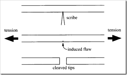
A general strategy involved in the technique of fiber optic cleaving is known as the scribe-and-tension or scribe-and-break strategy. With the use of cutting tool made from materials such as diamond, sapphire or tungsten carbide, this process involves the introduction of a crack in the fiber, then followed by the application of tensile stress in the vicinity of the crack.
Cleaving technique
However, the specific implementations of the cleaving can be various thus lead to cleaves of different qualities. Some implementations may apply the tensile force uniformly across the cross section of the fiber while others might bend the fiber around a curved surface, causing excessive tensile stress on the outside of the bend. Besides, the crack in the fiber may also be generated in different ways: the crack may be introduced at a single point on the circumference or it may be generated all along the circumference of the fiber prior to the application of the tensile force. The circumferential introduction of the crack often allows fibers of considerably large diameters to be cleaved while maintaining high quality of the cleave.
Common Cleaving Tools
Basically, there are two kinds of cleaving tools which are commonly employed in fiber optic cleaving: pen-shaped scribe and mechanical cleaver.
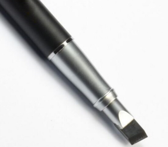
Pen-shaped scribe looks like a ballpoint pen, but with a small wedge tip made of diamond or other hard material that is used to scratch the fiber manually. After scratching the fiber, the operator pulls the fiber to break it. In essence, both the scribing and breaking process are under manual control, making it more dependent on operator technique and less predictable as they require operators to exert force manually for breaking the fiber. So, an experienced operator is required to produce good cleaves.
Fiber optic scribe
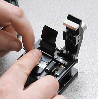
And the other tool is mechanical cleaver, which is widely used because it can produce nicer and more repeatable cleaves. This cleaver is much easier to use thus the specific training is not essential. Just clamp the fiber in the correct position into the cleaver. Then, a force is applied and the fiber gives a nice break at the scribe.
Mechanical cleaver
Conclusion
Since fiber splicing requires mating two fiber ends together, any defect of the ends would impact the performance of fiber splicing. So in order to achieve good fiber optic splices or terminations, it is extremely important to cleave the fiber properly. And a good cleaver can help better finish the whole cleaving process.

Thursday, June 16, 2016

Safety in Fiber Optic Installations

Fiber optic cables are now widely employed for the purpose of enhancing voice and data communication in many different applications. The flexibility of the technology is extraordinary, and advances in methods of communication have revealed even more uses for fiber optics. However, not all people, who install or maintain fiber optic cables, take proper safety precautions to avoid the hazards caused by fiber optics. Sometimes they just ignore the potential dangers of optical fiber. Unfortunately, accidents occur because of this neglect. This article will emphasize on introducing some common hazards that come with fiber optic installations and offering rules for safe installation.

Hazards of Working with Fiber Optics
The part will describe elements involved in safety protection issues when working with fiber optics. These are eye safety, bare fiber safety and other considerations for safety.

Eye Safety
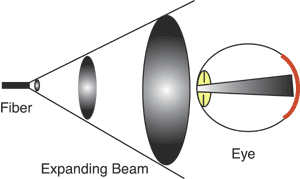
Many people are concerned that the most dangerous part of fiber-optic work was the chance you might get your eyes harmed by laser light in the fiber. However, in fact, most fiber-optic systems do not have sufficient power to cause harm to your eyes and the light coming out of a fiber is expanding, so the farther you are away from the end of the fiber, the lower the exposure.
Eye safety
However, it’s not a good idea to look into a fiber unless you know no source is being transmitted down it. You should always check the fiber with a power meter before examining it. The real issue of eye safety is getting fiber scraps into the eye. During the process of termination and splicing, you will be continually exposed to small scraps of bare fiber. And these scraps are very dangerous. Once they get into your eyes, they are very hard to flush out and will probably lead to a trip to the emergency room at the hospital. Whenever you are working with fiber, wear safety glasses!

Bare Fiber Safety
The fibers themselves are a very serious hazard since they are small pieces of glass. If possible, use a dark plastic mat for a work surface, which will make it easier to see the fibers you are working with and handle them more carefully.
When trimming, stripping, or cutting fibers, tiny fragments can penetrate the skin and become embedded, causing a serious irritation. Ingested fibers can cause internal damage since they are light enough to float in air. Because of this, workers should not eat or drink in a fiber optic work area since a fiber scrap could fall onto their food or in their drink.

Other Considerations for Safety
Fiber optic splicing and termination use various chemical cleaners and adhesives as part of the processes. And these substances should be properly handled. Note that fusion splicers use an electric arc to make splices, so one should ensure no flammable gases are contained in the space where fusion splicing is done. Smoking should not be allowed around fiber optic work.

Fiber Optic Installation Safety Rules
  • Keep all food and beverages out of the work area in case fiber particles are ingested
  • Wear disposable aprons to minimize fiber particles on your clothing. Fiber particles on your clothing can later get into food, drinks, and/or be ingested by other means.
  • Always wear safety glasses with side shields and protective gloves. Treat fiber optic splinters the same as you would glass splinters.
  • Never look directly into the end of fiber cables until you are positive that there is no light source at the other end. Use a fiber optic power meter to make certain the fiber is dark. When using an optical tracer or continuity checker, look at the fiber from an angle at least 6 inches away from your eye to determine if the visible light is present.
  • Only work in well ventilated areas.
  • Contact wearers must not handle their lenses until they have thoroughly washed their hands.
  • Do not touch your eyes while working with fiber optic systems until they have been thoroughly washed.
  • Keep all combustible materials safely away from the curing ovens.
  • Put all cut fiber pieces in a safe place.
  • Thoroughly clean your work area when you are done.
  • Do not smoke while working with fiber optic systems.
Conclusion
In conclusion, the awareness of safety should be raised among fiber optic installers, and each technician must adopt the best practices for safe handling of all fiber optic components to preserve the safe environment. Hope these simple fiber optic safety rules can contribute to building a healthy and sound work space.

Thursday, June 9, 2016

Coupler and Splitter Overview

It is generally accepted that fiber, connectors and splices rank are the most important passive devices. However, what closely following are tap ports, switches, wavelength-division multiplexers, bandwidth couplers and splitters. These devices divide, route or combine multiple optical signals. Splitter is named by the function of the device while coupler is named by its working principle.

Definition of Couplers
Fiber optic couplers either split optical signals into multiple paths or combine multiple signals on one path. Optical signals are more complex than electrical signals, making optical couplers trickier to design than their electrical counterparts. Like electrical currents, a flow of signal carriers, in this case photons, comprise the optical signal. However, an optical signal does not flow through the receiver to the ground. Rather, at the receiver, a detector absorbs the signal flow. Multiple receivers, connected in a series, would receive no signal past the first receiver which would absorb the entire signal. Thus, multiple parallel optical output ports must divide the signal between the ports, reducing its magnitude. The number of input and output ports, expressed as an N x M configuration, characterizes a coupler. The letter N represents the number of input fibers, and M represents the number of output fibers. Fused couplers can be made in any configuration, but they commonly use multiples of two (2 x 2, 4 x 4, 8 x 8, etc.). The following picture shows a typically optical coupler.
optical coupler

Definition of Splitters
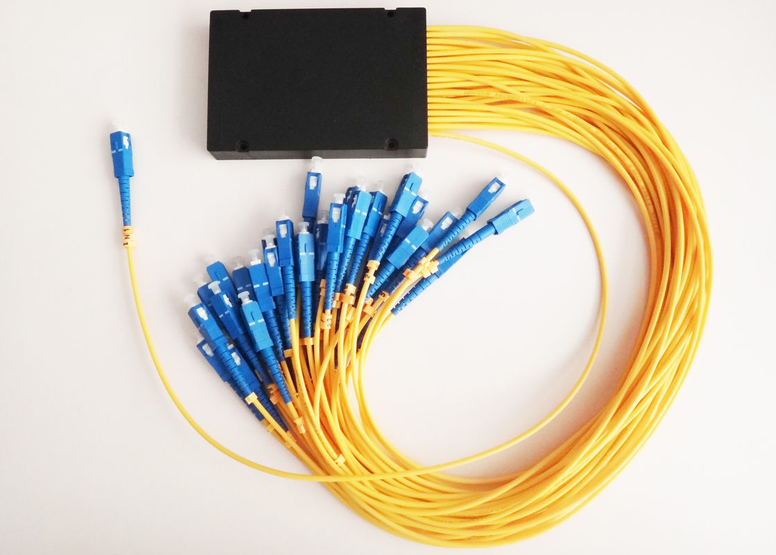
Fiber optic splitter is a device that splits the fiber optic light into several parts by a certain ratio. The simplest couplers are fiber optic splitters. These devices possess at least three ports but may have more than 32 for more complex devices. Fiber optic splitters are important passive components used in FTTx networks. Two kinds of fiber splitters are most used: one is the traditional fused type fiber optic splitter FBT splitter, which features competitive prices. And the other is PLC fiber optic splitter, which is of compact size and suit for density applications.
Just like fiber patch cable, fiber splitters are usually with 0.9mm, 2mm or 3mm cables. 0.9mm outer diameter cable is mostly used in stainless steel tube package fiber optic splitters, while 2mm and 3mm cables are mostly used in box type package fiber splitters. Based on working wavelength difference there are single window and dual window fiber optic splitters. And there are single mode fiber splitter and multimode fiber splitter. The picture below shows an optical splitter.
optical splitter

Coupler and Splitter Applications
Optical coupler is generally used in applications that require links other than point-to-point links, which includes bidirectional links and local area network. (LAN). Moreover, it serves as an important components used in WDM systems to route and split signals, monitor the network, or combine signal and pump wavelengths for feeding optical amplifiers.
Fiber optic splitter can be used for FTTx/PON application. This helps to reduce the physical fiber usage or the basic quantity of required fibers. A single fiber can be split into many branches to support multiple end users. The strain on the fiber backbone can be greatly decreased through the application. In addition, fiber optic splitter can also be employed in the maintenance of long-haul network, cable TV ATM circuit or local area/metro area network.

Conclusion
To sum up, fiber optic couplers or splitters are available in a selection of styles and sizes to separate or combine light with minimal loss. This article has presented you some basic knowledge related to couplers and splitters and may help you select the right one that most satisfies your need.

Fundamentals of Power over Ethernet (PoE)

With the introduction of new Ethernet-enabled devices expanding geometrically, the need to power these devices from standard AC power outlets has become a limiting factor. IP telephones, wireless access points, IP cameras and device servers are examples of devices limited by the need to have an AC power outlet nearby to plug in a DC power adapter. At best, power supply installation and wiring adds labor and results in the mess of extra wiring; worst case, the lack of nearby AC power means devices cannot be installed where they are needed.
In response to this need, IEEE developed IEEE802.3af to standardize a system of supplying low voltage power to networked devices via the communications line. It is more commonly referred to as Power over Ethernet (POE). This article focus on introducing some fundamental elements about PoE.

Basic Concepts of PoE
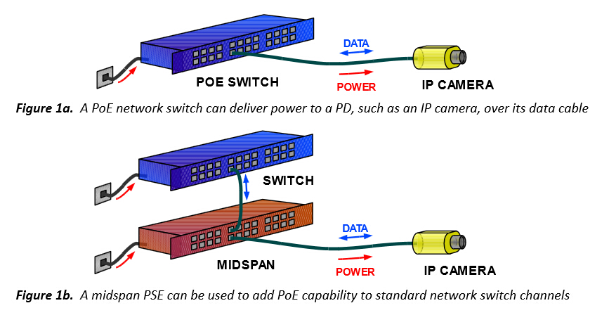
PoE is defined across a single network link that includes three basic components. The first one is an equipment delivering power to the cable (often referred to as a PSE, which stands for power sourcing equipment). The second component is a device receiving power from the cable (also known as a powered device, or PD). The third is the cable itself.
Typical PDs include IP cameras, wireless access points, and the PSE would normally be a PoE switch or a midspan power injector, patched in to add PoE capability to a non-PoE network switch channel or similar. These two configurations are shown in the following picture.
PoE

Advantages of PoE
The most prominent advantages of PoE are time saving and cost effective. By reducing the time and expense of having electrical power cabling installed, network cables do not require a qualified electrician to fit them, thus it can be located anywhere. Besides, it has great flexibility. Without being tethered to an electrical outlet, the PDs (IP cameras, wireless access points) could be located wherever they are needed most. Safety is the third advantage. PoE delivery is intelligent and it is designed to protect network equipment from overload, or incorrect installation. Also it has reliability and scalability. PoE power comes from a central and universally compatible source, rather than a collection of distributed wall adapters. It can be backed-up by an uninterruptible power supply, or controlled to easily disable or reset devices.

Applications of PoE
The original PoE application is VoIP phones, which have a single connection to a wall socket, and can be remotely powered down, just like with the older analog systems. PoE could also be used in IP cameras. It is ubiquitous on networked surveillance cameras where it enables fast deployment and easy repositioning. Wifi and bluetooth APs and RFID (radio frequency identification devices) readers are commonly PoE-compatible, to allow remote location away from AC outlets, and relocation following site surveys.

How PoE Works
PoE is designed to operate over standard network cable: Cat 3, Cat 5, Cat 5e or Cat 6 (often collectively referred to as Cat 5), using conventional RJ45 connectors. The principles of carrying electrical power over Cat5 are of no difference to those of other power distribution systems, but as the power is being transferred over light-duty cable for long distances, the effects of the power loss and voltage drop become significant.
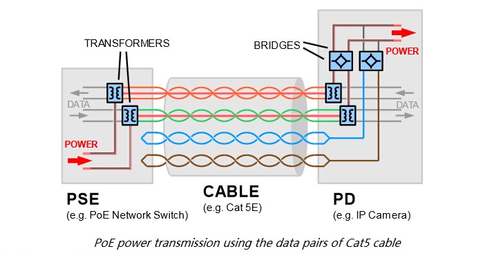
The arrangement and connection to the cabling used for PoE also differ slightly from conventional power wiring, in order to work around the existing standard for Ethernet data. Cat 5 network cables contain a bundle of eight wires, arranged as four twisted pairs shown in the following picture. In the most common type of Ethernet, 100BASE-T or Fast Ethernet, only two of the four pairs are used to carry data; each pair carrying a signal in one direction. These are known as the data pairs, and the remaining two are unused and are referred to as the spare pairs.
PoE working
Although each data signal can be carried within a single pair, PoE treats each pair of wires as a single conductor (a reason for this is that using both wires halves the overall resistance). As electrical current must flow in a loop, two pairs are required to allow power to be carried by the cable, and either the data or spare pairs can be used for this. The PD must be able to accept power from whichever pairs the PSE delivers it to.

Conclusion
PoE is a convenient and now ubiquitous method for delivering power to a wide variety of loads on standard Cat 5 Ethernet cables. It is no doubt that Power over Ethernet will become increasingly important in the near future.

Basic Knowledge About Optical Line Terminal (OLT)

With increasingly advanced and matured technologies in telecommunication network, Fiber to the Home (FTTH) has drawn much more attention of companies specialized in telecommunication nowadays. Generally, the FTTH broadband connections consist of two types of systems, known as Active Optical Networks (AON) and Passive Optical Networks (PON). And most of FTTH deployments are inclined to use a PON due to its low cost and high performance that can help to save a certain amount of money on fiber costs.
There are two major PON standards with the same basic topology structure: Gigabit Passive Optical Network (GPON) and Ethernet Passive Optical Network (EPON). A Gigabit Passive Optical Network (GPON) system generally contains an optical line terminal (OLT) at the service provider’s central office. As one of the indispensable components of PON, optical line terminal thus plays an essential role in the performance of the whole network connection. This article aims to provide some basic information related to OLT.

What Is OLT?
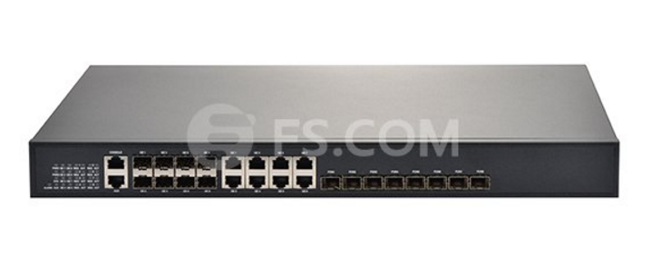
An optical line terminal (OLT), also known as optical line termination, acting as the endpoint hardware device in a passive optical network. The OLT contains a central processing unit (CPU), passive optical network cards, a gateway router (GWR) and a voice gateway (VGW) uplink cards. It can transmit a data signal to users at 1490 nanometers (nm). That signal can serve up to 128 ONTs at a range of up to 12.5 miles by using optical splitters.
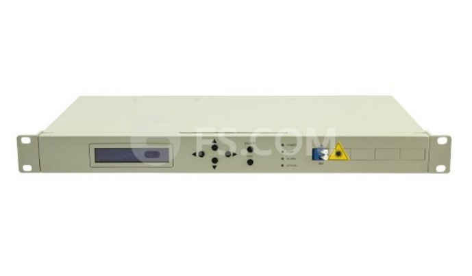
OLT with 8-PON ports

The Features of OLT
The OLT sends Ethernet data to the ONU, initiates and controls the ranging process, and records the ranging information. It provides numerous prominent features listed as follows.
  • A downstream frame processing means for receiving and churning an asynchronous transfer mode cell to generate a downstream frame, and converting a parallel data of the downstream frame into a serial data thereof.
  • A wavelength division multiplexing means for performing an electro/optical conversion of the serial data of the downstream frame and performing a wavelength division multiplexing thereof.
  • An upstream frame processing means for extracting data from the wavelength division multiplexing means, searching an overhead field, delineating a slot boundary, and processing a physical layer operations administration and maintenance (PLOAM) cell and a divided slot separately.
  • A control signal generation means for performing a media access control (MAC) protocol and generating variables and timing signals used for the downstream frame processing means and the upstream frame processing means.
  • A control means for controlling the downstream frame processing means and the upstream frame processing means by using the variables and the timing signals from the control signal generation means.

The Functions of OLT
OLT is generally employed for terminal connected to the fiber backbone. An OLT has two primary functions:
  • Converting the standard signals use by a FiOS service provider to the frequency and framing used by the PON system;
  • Coordinating the multiplexing between the conversion devices on the optical network terminals (OLTs) located on the customers’ premises.

The Role of OLT in GPON Network
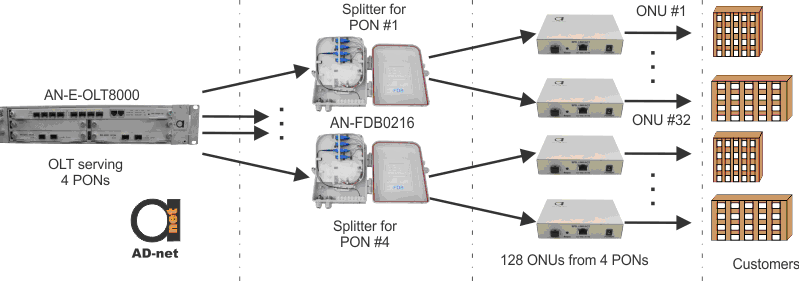
As it was mentioned above there are two functions performed by OLT, and the main function of OLT is to control the information float across the optical distribution network (ODN), going both directions, while being located in a central office. Maximum distance supported for transmitting across the ODN is 20 km. OLT has two float directions: upstream (getting an distributing different type of data and voice traffic from users) and downstream (getting data, voice and video traffic from metro network or from a long-haul network and send it to all ONT modules on the ODN.
Active PON
As we see from the picture above, OLT is designed for controlling more than one PON (in this example it serves for four independent networks). We can see that if every PON has 32 connections, OLT can distribute data to 128 ONTs. OLT has specific standard, so it would work with ONT from different manufacturers.

Conclusion
The OLT now has been widely adopted in fiber optic network access in counties, towns and villages. It can help efficiently reduce network construction cost, while simultaneously providing a guarantee on high bandwidth and high integration. And it is proved to be an ideal and constructive solution to FTTx projects.

Friday, June 3, 2016

Introduction to Erbium Doped Fiber Amplifier (EDFA)

In optical communication network, signal travels through fibers in every large distances without significant attenuation. However, when it comes to the distance up to hundreds of kilometers, to amplify the signal during transit becomes rather essential. In this case, an optical fiber amplifier is required to achieve signal amplification in long distance optical communication. This article aims to give a brief introduction to the most deployed fiber amplifier—Erbium doped fiber amplifier (EDFA).

What Is EDFA?
An EDFA is an optical or IR repeater that amplifies a modulated laser beam directly, without opto-electronic and electro-optical conversion. Generally speaking, EDFA is an optical repeater device that is used to boost the intensity of optical signals being carried through a fiber optic communications system.

Working Principle of EDFA
EDFA serves as a kind of optical amplifier which is doped with the rare earth element erbium so that the glass fiber can absorb light at one frequency and emit light at another frequency. An external semiconductor laser couples light into the fiber at infrared wavelengths of either 980 or 1480 nanometers. This action excites the erbium atoms. Additional optical signals at wavelengths between 1530 and 1620 nanometers enter the fiber and stimulate the excited erbium atoms to emit photons at the same wavelength as the incoming signal. This action amplifies a weak optical signal to a higher power, effecting a boost in the signal strength. The following picture shows 13dBm output C-band 40 channels booster EDFA for DWDM Networks.
EDFA

The Advantages of EDFA
The EDFA obtains the advantages of high gain, wide bandwidth, high output power, high pumping efficiency, low insertion loss, and it is not sensitive to the polarization state.
  • It provides in-line amplification of signal without requiring electronics, and the signal does not need to be converted to electrical signal before amplification. The amplification is entirely optical.
  • It provides high power transfer efficiency from pump to signal power.
  • The amplification is independent of data rate.
  • The gain is relatively flat so that they can be cascaded for long distance use. On the debit side, the devices are large. There is gain saturation and there is also the presence of amplified spontaneous emission (ASE).
The Applications of EDFA
The EDFA was the first successful optical amplifier and a significant factor in the rapid deployment of fiber optic networks during the 1990s. By adopting EDFA in conventional optical digital communication system applications, we can save a certain amount of optical repeaters. Meanwhile, the distance relay could also be increased significantly, which is vital for the long-haul fiber optic cable trunking systems. The EDFA is usually employed in these circumstances:
EDFA can be employed in the high-capacity and high-speed optical communication system. It offers a constructive and ideal solution for handling low sensitivity of receivers and short transmission distances because of a lack of OEO repeater.
In addition, EDFA can be adopted in long-haul optical communication system, such as land trunk optical transmission system and the submarine optical fiber cable transmission system. It helps to lower construction cost dramatically by reducing the quantity of regenerative repeaters.
Moreover, EDFA can also be employed in wavelength-division multiplexing (WDM) system, especially dense wavelength-division multiplexing (DWDM) system. It enables the problems of insertion loss to be solved successfully and reduces the influences of chromatic dispersion.

Conclusion
By far, being the most advanced and popular optical amplifier, EDFA has been widely adopted in the optical fiber communication networks. Featured by flat gain over a large dynamic gain range, low noise, high saturation output power and stable operation with excellent transient suppression, it surely will capture a rather vital and indispensable position in optical communication in the near future.

Thursday, June 2, 2016

Basic Knowledge About Fiber Optic Attenuator

It seems to be a commonplace for us to use an amplifier in fiber optic transmission which helps to improve signal electricity. However, it may occur sometimes that there is just too much light delivering through a fiber optic receiver and should better be reduced. In this case, a component known as fiber optic attenuator can help to reduce the power level of the signal. This article will focus on describing the fiber optic attenuator in details from the perspective of its types and applications.

What Is Fiber Optic Attenuator?
A fiber optic attenuator, generally known as optical attenuator, is a passive device used to reduce the power level of an optical signal. It can be adopted in both free space and in an optical fiber. Besides, to employ a fiber optic attenuator in single-mode long-haul application contributes to decreasing the chance of optical overload at the receiver.
By means of absorption, reflection, diffusion, scattering, deflection, diffraction and dispersion, etc, the fiber optic attenuator works efficiently to reduce the power of the signal. Optical attenuators usually function by absorbing the light, that resembles sunglasses absorb extra light energy. There exists a working wavelength range in which they absorb the light energy equally. They should not reflect the light since that could cause unwanted back reflection in the fiber system.

The Types of Fiber Optic Attenuator
There are a number of different forms of fiber optic attenuators by various classified methods, but basically, fixed attenuators and variable attenuators serve as the most common types that we can find in the market.

Fixed Attenuator
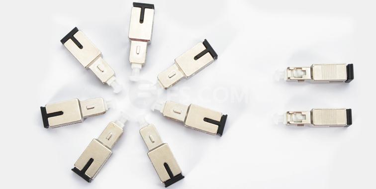
Fixed attenuator, as the name of which has indicated clearly, is designed to have an unchanging level of attenuation. It can theoretically be designed to provide any amount of attenuation that is desired. Fixed attenuator are typically used for single-mode applications and it consists of two groups: in-line type and connector type. In-line type appears like an ordinary fiber patch cable with a fiber terminated by two connectors. Connector type attenuator looks like a bulk head fiber connector, which has a male end and a female end as well. Fixed attenuator mates to regular connectors of the identical type such as FC, ST, SC and LC. The picture below shows a fixed male-female-SC/UPC SM 10dB fiber optic attenuator.
fixed attenuator

Variable Optical Attenuator
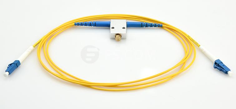
Variable optical attenuators generally use a variable neutral density filter. It has advantages of being stable, wavelength insensitive, mode insensitive, and offering a large dynamic range. Variable optical attenuator is generally used for testing and measurement, but it is also widely adopted in EDFAs (Erbium-Doped Fiber Amplifier) for equalizing the light power among different channels. Basically, there are two types of variable attenuators: stepwise variable attenuator and continuously variable attenuator. Stepwise variable attenuator can change the attenuation of the single in known steps such as 0.1 dB, 0.5 dB or 1 dB. Continuously variable attenuator produces precise level of attenuation with flexible adjustment. Thus, operators are able to adjust the attenuator to accommodate the changes required quickly and precisely without any interruption to the circuit. The following picture shows LC/UPC to LC/UPC variable fiber optic VOA in-line attenuator 0-60 dB.
variable optical attenuator

The Applications of Fiber Optic Attenuator
Fiber optic attenuator can be used to test power levels margins by temporarily adding a calibrated amount of signal loss. Besides, it is often installed permanently to properly match transmitter and receiver levels. And the sharp bends stress optic fibers and can cause losses.

Conclusion
From what we introduced above, you may have had a better understanding of the basic elements related to fiber optic attenuators. As an essential device in fiber optic transmission, it plays an indispensable role in controlling the power level of the optical signal. Those basic knowledge mentioned above may help provide a guideline to select the right fiber optic attenuator that matches the required applications precisely.

Outside Plant Fiber Optic Installations

Fiber optic has been widely used in the field of communication such as telecom, CATV, LAN, industrial, etc. However, even within communications applications, they are differ greatly in use and in methods of installation. For example, there are “outside plant” (OSP) fiber optics used in telephone networks, CATV, metropolitan networks, utilities, etc. or “premise” fiber optics adopted in buildings and campuses. And there exists fiber on “platform” like cars, planes and ships. Fiber optic is not all the same. This article will mainly focus on OSP installation in details.

What Is Outside Plant (OSP)
A significant amount of fiber optics are used in telephone companies, CATV and the Internet. In fact, all of this fiber optic is single-mode fiber and most of it is adopted in outside buildings. It hangs from poles, or it is buried underground, pulled through conduit or even submerged underwater. Most of it goes relatively long distances, from a few hundred feet to hundreds of miles. Outside plant cables often have very high fiber counts, up to 288 fibers or more. Cable designs are optimized for the application: cables in conduit for pulling tension and resisting moisture, buried cables for resisting moisture and rodent damage, aerial for continuous tension and extreme weather while undersea for resisting moisture penetration.

OSP Fiber Optic Installation
After designing fiber optic networks, there comes the next step—to install it. Outside plant installation of fiber optics can be a diverse process, as it may include placing aerial or underwater cable, direct-buried cable, cable in conduit or installing conduit or innnerduct and then pulling cable.
OSP cables are generally loose tube, ribbon or slotted core design. And their jackets are chosen to withstand an outdoor environment appropriate for the application. Strength members must be strong enough to absorb all the tension loads in the installation process or long term loads from aerial installation. Cables usually include fiberglass rod stiffeners in the center to prevent kinking. Jackets may be doubled with armor between them to prevent rodent penetration or crushing or strength member to allow pulling by the jacket.
OSP installations in conduit may require lubrication to reduce frictional loads and/or intermediate pulls. Intermediate pulls require pulling the cable to a point, laying on the ground in a "figure 8" pattern to prevent putting a twist in the cable, then pulling the next section.

Preparing for Outside Plant Installation
As we have mentioned above, OSP installation of fiber optics is rather diverse, and it is the diversity that makes it extremely important for the contractor to know the route of the cable to be installed intimately. Just as the estimator who should walk the route before beginning the estimating process, the contractor needs to see for themselves the actual situations they are going to encounter. That inspection allows them to determine what problems may be encountered, what special equipment may be needed and even double check that all the permits needed are in order.

Hardware and Equipment
OSP installation may need to position the supporting structures before starting the cable placement. New conduit or innerduct may need to be buried, or conduit already in place may need to be checked, old cables removed and new innerduct installed. Some buried cables even may require the installation of manholes or controlled-environment vaults for equipment and conduit.
hardware and equipment
Once the infrastructure is in place and the cabling pulled, it is time to splice the fiber optic. Now, scheduling the availability of appropriate fiber optic equipment is the concern. If the cable is to be spliced outdoors, a splice trailer is normally used, unless splices are being made on a pole or in a bucket, where a tent may be required in bad weather.
Each splice must be verified with an optical time-domain reflector (OTDR) test. Preferably, testing is done as each splice is made. To be efficient, a splicer will be on the job site, and a test tech will be at the other end of the cable with an OTDR to verify each splice. Splicing machines give an estimate of splice loss, but going back later, opening a splice closure and resplicing is an expensive proposition.

Termination
Cables will be terminated inside facilities where they will connect to communications equipment. OSP cables generally do not meet National Electrical Code flammability requirements, so the cable entering a building must be terminated or spliced to indoor cables soon after entry. Some OSP cables have double jackets, an outer one for outdoors and an inner one rated for indoor use, so the outer jacket can be stripped off inside the building and the cable run to the equipment room. Cables terminated in pedestals or vaults do not have this requirement.
Generally, single-mode OSP cables will be terminated by splicing pigtails onto each fiber, and splices will be placed in a splice closure. Multimode fibers can be handled the same way or terminated directly onto the fibers. Most OSP cables will require installing a breakout kit, which sleeves each fiber in a tube rugged enough for direct termination.

Safety
OSP safety is a very critical issue. Routes should be cleared with “One Call” or “Call Before You Dig” services to ensure no buried cables or pipes are in the proposed route. Installers working with cable-placing machinery need to be well trained in how to operate them safely. Aerial installations are particularly dangerous, since poles usually have electrical cables too close for comfort. Every OSP job should have posted safety procedures and all personnel should be briefed in their use.

Conclusion
In conclusion, with the advent of fiber optics used in communication networking, outside plant fiber optic installation has become a common phenomenon. What we discussed in this article may simply provider you an introduction and guideline to OSP installation, the real installation environment can be more complicated and time-consuming. So specialized personnel  are essential to ensure smooth and successful OSP installation.

Wednesday, June 1, 2016

Introduction to Passive Optical Network

It is universally known that fiber optics transmit data by light signals. And as this data moves across a fiber, there needs a way to separate it so that it gets to the proper destination. Generally, there exist two essential types of systems that make fiber-to-the-home broadband connections possible, which are active optical networks (AON) and passive optical networks (PON). Both of them provide ways to separate data and route it to the proper place. Nowadays, service providers invest billions of dollars in their access networks to meet the ever increasing demand for high-bandwidth broadband. In addition to technology longevity, service providers also like to see technology evolution to ensure future consumer demands can be met by staying within the same technology family. Consequently, the development of passive optical networking is on the rise.

The Definition of PON
A passive optical network (PON) is a system that brings optical fiber cabling and signals all or most of the way to the end user. It is a telecommunication technology that implements a point-to-multipoint architecture, in which unpowered fiber optic splitters are used to enable a single optical fiber to serve multiple end-points such as customers, without having to provision individual fibers between the hub and customer. The system can be described as fiber-to-the-curb (FTTC), fiber-to-the-building (FTTB), or fiber-to-the-home (FTTH).
PON
A PON consists of an optical line termination (OLT) at the service provider’s central office and a number of optical network units (ONUs) near end users. Typically, up to 32 ONUs can be connected to an OLT. The passive optical network simply describes the fact that optical transmission has no power requirements or active electronic parts once the signal is going through the network.
A PON system makes it possible to share expensive components for FTTH. A passive splitter that takes one input and splits it to broadcast to many users, which help cut the cost of the links substantially by sharing, for example, one expensive laser with up to 32 homes. PON splitters are bi-directional, that is signals can be sent downstream from the central office, broadcast to all users, and signals from the users can be sent upstream and combined into one fiber to communicate with the central office.

Difference Between AON and PON
As it was mentioned above, AON and PON serve as the two main methods of building CWDM and DWDM backbone network. Each of them has their own merits and demerits.
An active optical system uses electrically powered switching equipment, such as a router or a switch aggregator, to manage signal distribution and direction signals to specific customers. This switch directs the incoming and outgoing signals to the proper place by opening and closing in various ways. In such a system, a customer may have a dedicated fiber running to his or her house. The reliance of AON on Ethernet technology makes interoperability among vendors easy. Subscribers can select hardware that delivers an appropriate data transmission rate and scale up as their needs increase without having to restructure the network. However, AON require at least one switch aggregator for every 48 subscribes. Since it requires power, an active optical network inherently is less reliable than a passive optical network.
A passive optical network, on the other hand, does not include electrically powered switching equipment, instead, it uses optical splitters to separate and collect optical signals as they move through the network. A PON shares fiber optic strands for portions of the network. Powered equipment is required only at the source and receiving ends of the signal. PONs are efficient since each fiber optic strand can serve up to 32 users. Besides, PONs have a low building cost compared with active optical networks along with lower maintenance cost. However, PONs also have some demerits. They have less range than an AON, which means subscribes must be geographically closer to the central source of the data. When a failure occurs, it is rather difficult to isolate it in a PONs. Moreover, because the bandwidth in a PON is not dedicated to individual subscribers, data transmission speed may slow down during peak usage times in an effect known as latency. And latency would quickly degrade services such as audio and video, which need a smooth rate to maintain quality.
AON & PON

The Benefits of PON
As early as the year 2009, PONs began appearing in corporate networks. Users were adopting these networks because they were cheaper, faster, lower in power consumption, easier to provision for voice, data and video, and easier to manage, since they were originally designed to connect millions of homes for telephone, Internet and TV services.
Passive Optical Networks (PON) provide high-speed, high-bandwidth and secure voice, video and data service delivery over a combined fiber network. The main benefits of PON are listed below:
  • Lower network operational costs
  • Elimination of Ethernet switches in the network
  • Elimination of recurring costs associated with a fabric of Ethernet switches in the network
  • Lower installation (CapEx) costs for a new or upgraded network (min 200 users)
  • Lower network energy (OpEx) costs
  • Less network infrastructure
  • You can reclaim wiring closet (IDF) real estate
  • Large bundles of copper cable are replaced with small single mode optical fiber cable
  • PON provides increased distance between data center and desktop (>20 kilometers)
  • Network maintenance is easier and less expensive
  • Fiber is more secured than copper. It is harder to tap. There is no available sniffer port on a passive optical splitter. Data is encrypted between the OLT and the ONT.
Conclusion
From what we have discussed above, you may at least have a brief understanding of the passive optical network. In fact, PON has been around for many years in the service provider space. Now PON is finally making its way into the enterprise space by providing opportunities for customers deploying new infrastructure or new construction. The technology is catching on. Now, PON mainly captures the commercial market, which performs well in healthcare, college campuses, hotels and office buildings. A PON network eliminates the need for switches and a wiring closet, which means fewer points of failure.