Friday, April 29, 2016

How to Clean the Data Center?

Dust and dirt in data center could be a nightmare that troubles most of the telecom engineers. Now and then as they try to put their fingers on a distribution cabinet or a patch panel in a data center, the fingers are always stained by dust or dirt. However, this annoying situation is not rare for those engineers working in the field of telecommunication. Some of them may have realized the importance of cleanliness in data center, but they seldom take action to remove the dust and dirt. It means people simply attach less importance to keep the data center clean enough. Some contaminants can easily be seen or checked by eyes and hands, but there are still myriads of them existing inside the equipment which may lead to disastrous consequences such as overheating as well as various network failures if no proper action was taken to clean.

The Importance of Cleaning Data Center
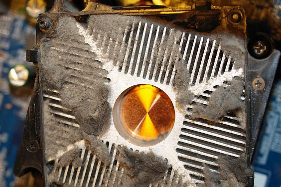
Imagine what would happen if there is no regular cleaning in the data center? As it was mentioned above, the most direct result of contaminant is overheating. Since dust and pollutants in the data center are usually light-weight, If there is air flow, dust or dirt will move with it. The cooling system of the data center is depending largely on server fan which can bring the dust and dirt into the cooling system. The accumulation of these contaminant can cause fan failure or static discharge inside equipment. The heat dissipation will need more time and heat emission efficiency is limited. The following picture shows the contaminant at a server fan air intake that can explain this phenomenon.

the contaminant at a server fan air intake

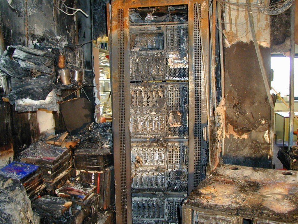
As the cooling system is affected by the dust and dirt, the risk of the data center increases largely. Contaminants will capture every possible place in the data center where they are capable of. In addition, data center nowadays relies heavily on electronic equipment and fiber optic components like fiber optic connectors, which are very sensitive to contaminants. Problems like power failures, loss of data and short circuit might happen if the contaminants are not removed completely. What’s worse, short circuit might cause fire in the data center, which could lead to irreparable damage. The following picture shows the data center after a fire. It is really a disaster for the data center managers.

the data center after a fire


Dust and dirt can also influence the life span of data center equipment as well as their operation. The uptime of a data center may decrease if there are too many contaminants. Cleaning the data center regularly would help to reduce data center downtime and extend the life span of data center infrastructure equipment. It is proved to be cost efficient and energy saving comparing with restarting the data center or repairing the equipment.
Furthermore, data center cleanliness can offer an aesthetic appeal to a clean and dust-free environment. Although it is not the main purpose, a clean data center can present a more desirable working environment for telecom engineers, especially for those who need to install cable under a raised floor or working overhead racks and cabinet. No one would reject a cleaning data center.

Contaminants Sources of Data Center
There is no doubt that data center cleanliness is necessary. But how to keep the data center clean? Before taking action, source of contaminants in the data center should be taken into consideration. Generally, there are two main sources. One is inside the data center, and the other is from outside of the data center. The internal contaminants are usually particles from air conditioning unit fan belt wear, toner dust, packaging and construction materials, human hair and clothing as well as zinc whiskers from electroplated steel floor plates. The external sources of contamination include cars, electricity generation, sea salt, natural and artificial fibers, plant pollen and wind-blown dust.

Data Center Cleaning and Contaminants Prevention
Having known where the dust and dirt come from, here offers some suggestions and tips to reduce the contaminants.
  • Reduce the data center access. It is recommended that limited access to only necessary personnel can reduce the external contaminants.
  • Sticky mats should be used at the entrances to the raised floor, which can eliminate the contaminants from shoes largely.
  • Never unpack new equipment inside the data center, establish a staging area outside the data center for unpacking and assembling equipment.
  • No food, drink or smoking in the data center.
  • Typically all sites are required to have fresh air make-up to the data center, remember to replace on a regular basis.
  • Cleaning frequency depends on activity in the data center. Floor vacuuming should be more often as the traffic in the data center increased.
  • Inspect and clean the fiber optic components regularly, especially for fiber optic connector and interface of switches and transceivers.
  • The inside and outside of racks and cabinets should be cleaned.
Conclusion
Data center operates like an information factory nowadays as it processes countless data and information as well. Therefore, the cleanliness of the data center becomes increasingly important. If this essential “factory” is polluted by dust and dirt, it will eventually fail to provide reliable and qualified services. Not to mention that a clean data center could ensure a much more extended life span of equipment and applications thus to effectively save a great amount of money for the maintenance.
Thursday, April 28, 2016

Three Necessities for Smooth Migration to 40G

As applications such as Big Data, Cloud and Internet of Things are brought to a variety of industries, the demand for high speed transmission is increasing rapidly ever since. Therefore, the 10GbE (Gigabit Ethernet) can no longer fulfill these requirements. So there arrives at a consensus in the industry for transmission network migration to 40/100G. The 40G severs as an excellent and economical solution to satisfy the current need for data transmission, whereas the 100G is proved to be less cost efficient and the technology of it is still immature, which makes the 100G currently beyond the reach of average companies. Nowadays, the servers are well prepared to carry the transmission of 40 Gbps in many data centers since the core technologies of 40G are advanced step by step. Besides, the cost of deploying 40G decreases as an increasing number of manufacturers are competing with each other for the 40G market.
Comparing with 1G migrating to 10G, there exists a much larger span for 10G migration to 40G with regard to transmission data rate and technologies. Thus, the deployment of 40G migration is much more complicated than that of 10G. Three factors must be taken into consideration to increase the reliability and manageability for 40G migration, which are fiber optic transceiver, transmission media, and pre-terminated MPO assemblies.

Fiber Optic Transceiver
Fiber optic interconnection plays an indispensable role in today’s telecommunication network. Photoelectric conversion pertains to a necessary part of fiber optic network. The function of fiber optic transceiver is photoelectric conversion, which makes it one of the most commonly used components in the data center. Without it, the data center cannot run normally.

QSFP-40G-LR4 transceiver

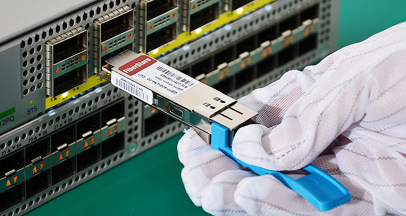
As for 40G migration, transceivers of two different package forms are commonly used: QSFP+ transceiver (Quad Small Form-factor Pluggable Plus transceiver) and CFP transceiver (C Form-factor Pluggable transceiver). QSFP+ transceiver is more popular in 40G application. A single 40G fiber optic transceiver may not be expensive. However, thousand of optical transceivers might be needed for a medium-sized data center, thus the total cost of optical transceivers can be a large sum of money. While the switch market has already been monopolized, the transceiver market is not. Third party transceivers that are compatible with various types of switches are offered in today’s market. They can perform as well as the original brand transceivers with less cost. So, many data centers begin to take compatible transceivers as one of their options. As cost serves as one essential aspect in 40G optical transceiver selection, quality also attaches more importance since not all the third party transceivers are created equal. Selecting the 40G compatible transceivers from a company that assures 100% compatibility and interoperability is necessary. The picture above shows the testing of Cisco compatible QSFP-40G-LR4 transceivers on a Cisco switch to ensure its compatibility and interoperability.

Transmission Media
40G standards of IEEE have already been announced several years ago. To meet various situations, there exists standards for different transmission media. Although fiber optic cable is becoming more and more popular, there is still a place for copper cable in the data center. Standards for both copper and fiber optic are being used. Commonly used 40G Ethernet media systems including:
  • 40GBASE-CR4: 40Gb/s Ethernet over copper cable in short transmission distance.
  • 40GBASE-SR4: 40Gb/s Ethernet over four short-range multimode fiber optic cables.
  • 40GBASE-LR4: 40Gb/s Ethernet over four wavelengths carried by a signal long-distance single-mode fiber optic cable.
Then, here comes the old question: fiber optic cable or copper cable, which one should be adopted in 40G migration? Although copper is cheaper in terms of the price, it can only support 40G transmission limited to several meters. Whereas single-mode fiber optic cable supports the 40G transmission distances up to 10km. For multimode fiber optic cables, OM3 and OM4 are supposed to support short distance transmission. The longest distance that OM3 can support for 40G transmission is 100 m, while OM4 can support a longer 40G transmission distance of 150 m. The selection of transmission media should depend on the specific applications.

pre-terminated-MTP-assemblies

MPO Assemblies for 40G
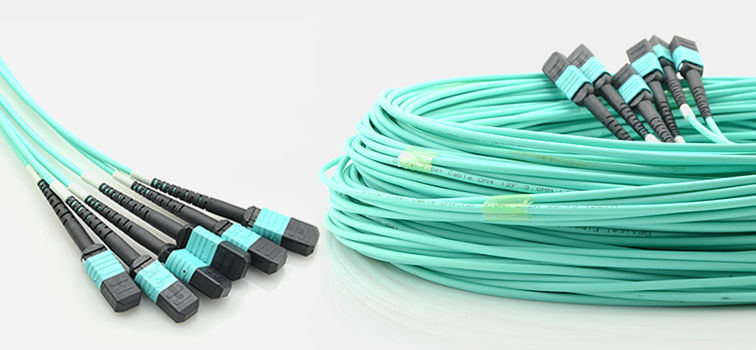
According to the IEEE standards, 40G multimode Ethernet transmission uses four multimode fiber optic cables. The IEEE 802.3ba standard also specifies multi-fiber push-on (MPO) connector for standard-length multimode fiber connectivity. Most of the 40G multimode Ethernet transceivers are based on the MPO technology. It is wise to increase fiber optic density by using MPO technology, but a new problem comes up. Cabling and splicing difficulties in data center increase with the accelerating number of fiber. Unlike traditional two-strand fiber connections, MPO connectors cannot be terminated easily. So, most of the data centers choose the pre-terminated MPO assemblies (as shown in the picture above) in 40G deployment, which is more reliable and can save human labor. Before cabling, it would be time-saving and cost-efficient to determine the cabling lengths and customized pre-terminated MPO assemblies with manufacturers.

Conclusion
During the process of migration to 40G, to select a compatible third party transceiver of high quality would contribute to decrease the money and time spending on data transmission. With the combination of specific applications and characteristics of 40G transmission media, it helps to achieve a rather economical and reliable 40G deployment task. Furthermore, pre-terminated MPO assemblies can necessarily ensure flexible and manageable cabling in 40G deployment. 40G has already become the tide of today’s data transmission and it plays a significant role in the history of network transmission.


Wednesday, April 27, 2016

Introduction to Single-mode Fiber Patch Cords

Fiber optic patch cords refer to those fiber optic cables with connectors on both ends, which can be directly and rapidly connected to computers or other equipment. With a thick layer of protection, patch cords are usually used to connect the optical transmitter, receiver as well as the terminal box. It is widely accepted that in terms of transmission medium, the fiber patch cords can be defined into two categories: single-mode fiber patch cords and multimode fiber patch cords. This article aims to briefly introduce the single-mode fiber patch cords.
The Definition of Single-mode Fiber Patch Cords
Single-mode fiber patch cords contain a small core of 9/125 um and have only one pathway of light. Instead of simply bouncing the light of the edge of the core, the single-mode patch cords realign the light toward the center of the core with only a single wavelength of light passing through its core. Generally, the color of single-mode fiber patch cord is yellow. It is most often used in long-distance, high bandwidth network connections spread out over extended areas, usually longer than a few miles.
The Features of Single-mode Fiber Patch Cords
Single-mode fiber patch cords can achieve lower attenuation and thus obtain the ability for the signal to travel faster and further. Besides, it also has several other advantages:
  • 1. Low insertion loss and high return loss
  • 2. Excellent environmental adaptability
  • 3. Good performance endurance under changing circumstance
  • 4. Higher speed data transmission with longer distance
  • 5. Simplex and duplex assemblies
The Types of Single-mode Fiber Patch Cords
As for the types of single-mode fiber patch cords, classified by connector construction, they can be divided into LC, FC, SC, ST, MTRJ, E2000 and MU fiber patch cords, etc. Each of these single-mode fiber patch cords are available both in simplex and duplex patch cords. So, the following part will focus on the introduction to simplex and duplex single-mode fiber patch cords.
Simplex Single-mode Fiber Patch Cords
Simplex single-mode fiber patch cords consist of a single strand of glass or plastic fiber. It is generally adopted in devices where only a single transmit and/or receive line is required, which means the data barely send in one direction. For instance, TV and radio broadcasting employed simplex fiber patch cords to achieve one direction signal transfer. During the process, information flows only from the transmitter site to multiple receivers. The picture below is a SC-SC simplex single-mode fiber patch cable.
SC-SC simplex single-mode fiber patch cable
Duplex Single-mode Fiber Patch Cords
Duplex single-mode fiber patch cords consist of two strands of glass or plastic fiber. It is often seen in a zipcord construction format. A duplex fiber patch cable can be regarded as two simplex cables having their jackets conjoined by a strip of jacket material. This kind of patch cable is mostly used for duplex communication that a separate transmit and receive are required between devices, which indicates that these two connected parties can communicate with each other in both directions. Duplex fiber patch cords are usually adopted in the field of telecommunication. The picture below is a LC-SC duplex single-mode fiber patch cable.
LC-SC duplex single-mode fiber patch cable
The Application of Single-mode Fiber Patch Cords
As it was mentioned at the beginning of the article, the single-mode fiber patch cord is often used to achieve long-distance and high bandwidth data transmission with little integrity loss. This type of cable is extensively adopted in telecommunication network, high speed metropolitan access network as it supports high speed multi channel video, data and voice services.
Conclusion
From what discussed above, you might have a better understanding of single-mode fiber patch cords. There are still some elements that should be taken into consideration while choosing the suitable patch cords. Fiberstore supplies a large quantity of single-mode fiber patch cords with the coverage of all the types. To learn more about single-mode fiber patch cords, please kindly visit the website at www.fs.com or contact over sales@fs.com.

Wednesday, April 20, 2016

Necessities to Achieve 10Gb Ethernet Deployment

Immediately after the standard of 10Gb Ethernet was ratified, numerous large companies began to apply it straightly to the central field of their business, data centers, and server farms for the purpose of supporting bandwidth with higher speed and some crucial applications. With the advancements in 10GbE technologies, the increased requirements of bandwidth, and the growth of enterprise applications in recent years, the influence and usage of it are no longer limited within merely enterprise but has stretched to mid market networks as well. As the deployment of 10GbE becomes increasingly popular than before, ten things are really crucial to realize the best use of it.
10GbE and the Server Edge to Achieve Better Efficiency
Enterprises usually work out to consolidate servers so that there is more space and power left to optimize their data centers as well as sever rooms. And this process often contains two steps: to combine the applications to fewer servers and to realize server visualization. The server visualization, which depends on networking and storage largely, enables some applications and operating systems on a single sever thus to make the best use of the processing power and resources.
10GbE SAN vs. Fiber Channel 
As one of the three types of storage in a network, SAN(Storage Area Network) obtains much flexibility when comparing with the other two, and severs as a better solution for both data centers and computing applications. However, only with high expense and specialized staffs can the SANs with Fiber Channel be well-equipped in large companies. Moreover, The iSCSL, as a new standard, helps to make 10GbE an appealing SAN interconnect fabric which can compare to Fiber Channel. The 10GbE performs well by reducing the cost, enhancing server management and improving disaster recovery.
10GbE and the Aggregation Layer
Compared with Gigabit Ethernet aggregation, the 10GbE use less fiber strands which is more cost-efficient. Besides, because of its greater capacity, the 10GbE thus can support large streams that generated by applications. The most important is that, by applying 10GbE, it can enable a longer deployment periods so as to reduce the bottlenecks. 10GbE and Fiber Cabling Choice
When deploying the fiber cable, there exists three important choices: firstly, the type of fiber cable that contains both the multimode MMF(Multi-Mode Fiber) and the single-mode SMF(Single-Mode Fiber). Secondly, the type of 10GbE physical interfaces. And thirdly, the 10GbE module form factors. Furthermore, If the type of the physical interface on both end of the fiber link is the same, form factor options can be inter operable.


10GbE and Copper Cabling Choices
Cooper cabling has been widely used for 10GbE since the standard of which advances at a rather high speed. For the time being there are three technologies for copper cabling with different price and capability and each of them has their own merits and demerits. For example, the CX4(10GBase-CX4), which is the first cooper standard in this field, is cost-efficiency as it enables a relatively low latency. And the SFP+ serves as the latest standard with low latency, small form factor and reasonable cost. As for the 10GBase-T, although it is promising, the technology still needs improvements to reduce its cost, power consumption and latency.
10GbE and the SFP+ Makeover
By combining the SFP+ compatible connectors and the copper cable, SFP+ direct attach cables can achieve a solution which is low-latency, energy-saving and cost-efficiency. With DAC, 10GbE connections in short distances can perform for the best. As for ToR applications, DAC is used to simplify rack cabling and termination, it makes the management of cable easier and much more flexible.
In conclusion, if users take these necessities into consideration, what we discussed above can help enterprises and companies to achieve a better 10GbE deployment experience.

Friday, April 15, 2016

Optical Transceivers

Optical Transceivers 
CXP Optical Transceiver
CXP is often used in the field of computer networking, referring to the hot-swappable input/output devices. It supports 100 Gigabit Ethernet and offers users a great number of high-density 100Gbps connectivity solutions to enable more flexibility of interface choice. The CXP module focus on use in data center, core-routing, and high-performance computing applications and the speed is supposed to reach up to 150Gbps links over multimode fiber.
QSFP28
The QSFP is a compact, hot-pluggable transceiver which is widely used in data communication applications. As the technique in the field of networking advances, a better version of the original one is developed, knowing as the QSFP to achieve higher data rates. The QSFP enables the data transmit rate to reach as high as 4×28Gbps, with the high port densities, the compact size and low power consumption, it improves the work efficiency to a large extent.
BiDi (Bi-Directional) SFP
The BIDI SFP refers to a compact optical transceiver module which can be used in both telecommunication and data bidirectional communication applications. As a popular industry format that captures a relatively large proportion of the market, it draws much attention of the fiber optic opponent manufacturers. Produced either with SC or LC simplex port, the BIDI SFP can be used for both transmission and receiving with the wavelength combination. Two different optics are necessary to form the link.
WDM
The WDM stands for wavelength-division multiplexing in the field of fiber-optic communication. By using laser light of different wavelength, it multiplexes some optical carrier signals onto one optical fiber. The WDM makes it possible for bidirectional communication over one strand of fiber as well as multiplication of capacity. The WDM is widely used to multiply the effective bandwidth of a fiber optic communications system, and with a fiber optic repeater device, it can become a cost-effective long-term solution.
CWDM
The CWDM refers to the coarse wavelength division multiplexing which is a technique used to combine multiple signals of different wavelength on laser beams for transmission along fiber optic cables. It owns fewer channels than that of DWDM. With channels at wavelengths spaced 20nm apart, it enables the use of low-cost, uncooled lasers. As the CWDM usually use lasers with lower precision, the CWDM system is much cheaper and consumes less power.
DWDM
The DWDM stands for the dense wavelength division multiplexing, which serves as a method to combine data from different sources together to an optical fiber. During this process, while on its own separate light wavelength, every signal is carried at the same time. The DWDM enables up to 80 or more separate wavelengths or channels of data to be multiplexed into a light stream transmitted on a single optical fiber. DWDM now is expected to be the central technology in the all-optical networks of the future.
 

Thursday, April 14, 2016

Common Transceivers in Optical Communication

XFP
The XFP is a 10 gigabit Small Form Factor Pluggable which uses optic fiber to achieve computer network and telecommunication in a relatively high speed. XFP modules support Ethernet, Fiber Channel, SONET, OTN and parallel optics links as well. And they can either work on a single wavelength or use multiple techniques. XFP now is widely used in optic communication around the world since it provides flexibility interface choice and can be adapted into various transmitter and receiver types, so the users have much more rights and flexibility to choose a proper transceiver to achieve the most efficient optical reach.

X2
X2 transceiver is the 10G fiber optic transceiver which is developed on the basis of the former Xenpak standard. The 10-Gigabit Ethernet X2 module is a hot-swappable I/O device that plugs into 10-Gigabit Ethernet ports. Its functions are similar with those of the Xenpak but with a smaller size, which enables it can be adapted to density installation. The X2 enhances the data transmission rate greatly and can function well even in long distance from 300meters to 40km. 10G X2 modules offer customers various of 10 Gigabit Ethernet connectivity options for data center, enterprise wiring closet, and service provider transport applications.
XENPAK
XENPAK is a MSA that is widely used to define a fiber-optic or weird transceiver module. Numerous network equipment manufactures and module makers support the XENPAK until the advanced technologies bring about more compact form factors such as XPAK and X2 with different mechanical properties. But these two newly emerged standard  shares the same electrical interface with XENPAK. The XENPAK modules are mostly used in physical layer interfaces that support both multi-mode fiber optic cables and single mode ones. It can achieve the transmission distances as far as 100meters to 80km.

QSFP
QSFP is short for Quad Small Form-factor pluggable, which is a compact hot-pluggable transceiver applied in data communication, allowing data rates from 4×10 Gbit/s. The QSFP is developed to satisfy the demand of the market for a more intensified pluggable solution, and numerous mature and crucial techniques that once used in XFP were applied in it. QSFP modules increase the port-density by 3 to 4 times when comparing to the SFP+ modules, for it supports data transmission in four ports at the same time at the speed of 10Gbps. The QSFP has become a standard which is applied by some manufactures.

CFP
The CFP stands for the Centum Form-factor pluggable which is a hot pluggable fiber optic transceiver. It is designed to transmit the digital signal at a relatively high speed. As much as 100G data transmission over ten wavelength- division- multiplexed lanes can be achieved by the CFP, and the transmission distance can reach up to 40km. Being conveniently assembled into and released from the host system, the CFP provide much flexibility for the users. With the improvement of technology, the CFP2 and CFP4 specification are developed with higher performance and higher density. Although they have similar electrical form as CFP,  the size of these two is 1/2 and 1/4 respectively smaller than the original specification.